 Jarrett
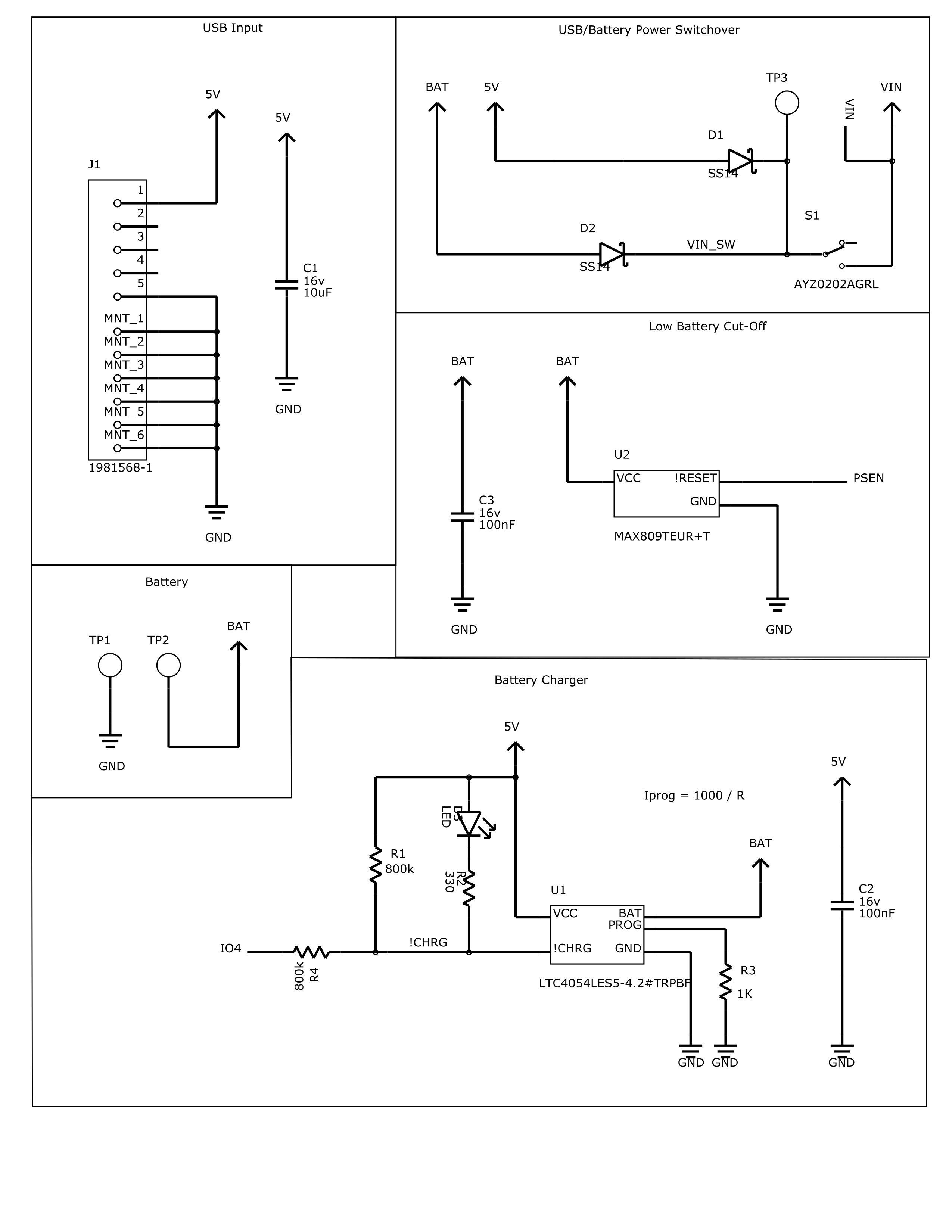
LiPo management circuitry is fairly complex, and I couldn't really find any one-chip solutions that weren't $15 for an IC. So I did it properly.
MicroUSB connector, with diodes to select for the higher of two voltages (3v-4.2v battery or 5V USB), to a power switch.
The MAX809 is a low voltage cutoff chip, so that when the LiPo sags below 3.0V, it'll disable to the power regulator and not damage your battery.
The LTC4054 is a LiPo battery constant current charger, to properly charge your battery when USB is plugged in. R3 can be changed to adjust the charge speed. Few of these values are set on the schematic, so don't use 1k, that would be very slow!
The charge indicator LED works according to how the datasheet specs, but there's also some clever connections to allow the ESP32 to be able to read charge status, if desired.
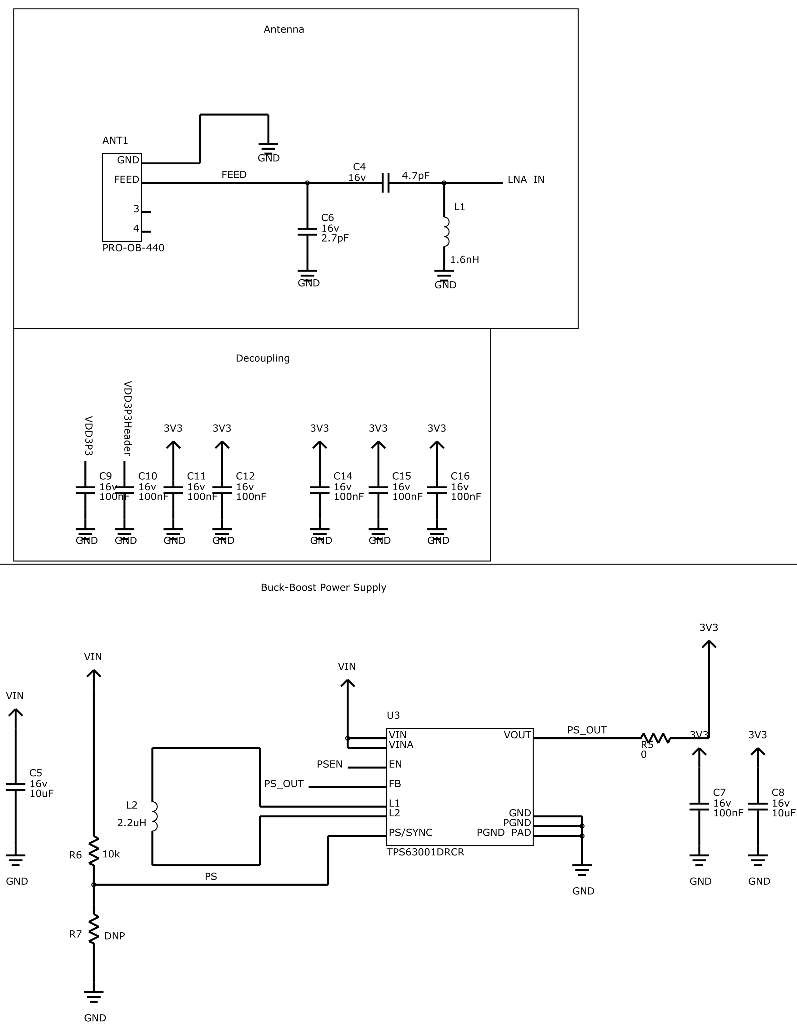
The antenna is a Proant 440 3D antenna for 2.4GHz. These values are certainly subject to tuning when the board arrives, and the inductor might not even end up being an inductor.
The ESP32 I used, a bare ESP-PICO-D4 has a whole bunch of power rails, so requires a bunch of decoupling caps, the usual. I probably won't bother populating a bunch unless they are required.
The TPS63001 is a buck-boost switch-mode power supply, outputting 3.3v and with an input that nicely brackets the 3.0v-5.0v range I'm targeting. Input voltage to this will probably be more like minimum 2.0v-2.6v due to my input diodes, but I might switch those to something fancier.
The output also has a 0-ohm resistor that I could sub out for an inductive choke if I need some better filtering.
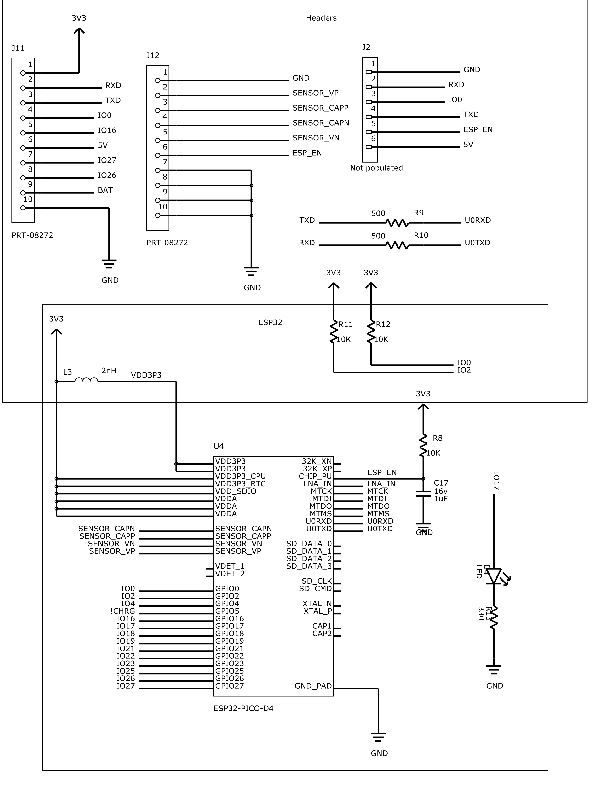
A bunch of headers. J11 and J12 are the castellated edges. Pins 7-10 on J12 are a liiiittle bit janky, because they intersect with my USB port's ground pads. They should make it hard to pull the connector off, though!
J2 I ended up leaving off the PCB, but it has all of the signals needed for programming. They were duplicated to some of the castellations, so no big deal.
And finally, the ESP-PICO-D4! Fairly self-explanatory. I was slightly choked I didn't have room for the JTAG headers.
Discussions
Become a Hackaday.io Member
Create an account to leave a comment. Already have an account? Log In.
Regarding the diode-based voltage switchover, there's actually a slightly more efficient way of selecting for the two voltages:
The USB still passes through a diode onto the power rail, but the battery voltage is gated by a P-Channel MOSFET, whose gate is connected to the 5V USB power.
If no USB power is present, the USB rail goes to 0V, turning on the P-Channel MOSFET - which will usually have a voltage drop smaller than most diodes!
With 5V present on the Rail though the MOSFET is fully turned off, and the diode lets USB power pass through.
At these voltages I'm also not sure if a buck-boost converter has considerably more efficiency than a LDO, but since we are talking about running the Battery to fairly low voltages the boost part is still good to have.
This is looking quite nice though!
Are you sure? yes | no
Totally! It was always my intention to characterise the efficiency vs a linear solution, but I had to shelve the project before I got around to it.
Also, spot on about the P-FET :)
I wrote about it recently, even:
https://jrainimo.com/build/2019/03/lipo-systems-with-usb-power/
Are you sure? yes | no
Just a question, how do you make sure the gate voltage goes to 0 when you disconnect the USB? Does it have a pull down resistor or something?
Are you sure? yes | no
Yes, you should use a high value resistor to ground. 100k?
Are you sure? yes | no
I have a question regarding D2 diode, which is supposed to help for when both battery and 5 volts is connected.
When both battery and 5 volts source are connected, D2 is going to have a tiny reverse current charging the battery. Based on your experience, can the reverse current cause any damage? Even if the battery is fully charged and the 5 Volt source remain connected for a long time?
Are you sure? yes | no
I hadn't considered that, because reverse leakage is typically very very small.
Just checking the datasheet of the SS14, and it has 0.2mA leakage at full reverse voltage rating (40v). So at the potential 2v difference, it'll be really really small. And I don't think I used those, I think I found something with better specs, but I don't have the part number offhand.
Are you sure? yes | no
Is it correct to assume that based on your experience nothing goes wrong?
Do you think for using the same design more testing should be carried out? Even if the reverse current is like super-duper low?
I am asking this to see how much testing I should do before integrating it in #Alpha V1: Open-Source Remote Controller .
Are you sure? yes | no
I would definitely say it's low enough to not worry about it - With the tiny reverse voltage level, current leakage will probably be similar to self-discharge of the battery. But before you use that design, see my reply to Xasin, above ^
Are you sure? yes | no
@Jarrett Thank you
Are you sure? yes | no