To be honest, this isn't the absolute first. Last year, when I watched Great Scott's video I had the idea for this, and a little later I tested it. I just set up an MCU to put out a PWM signal, hooked it up to a makeshift half-bridge (basically just an amplifier), pulled out a motor off my scrapheap and connected all. Motor phase 1 to ground, phase 2 to PWM output, phase 3 floating. Phase 2 and 3 monitored by my oscilloscope's two channels.
The result was something like this:
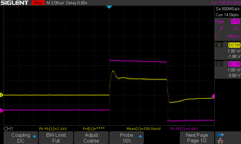
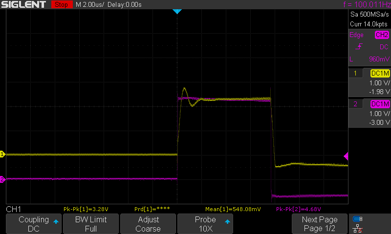
The driving signal CH2, and the floating lead CH1. Between taking these two screenshots I turned the rotor a little, but it was not moving when I took the pictures.
Small 3 phase motors have 3 or 4 contacts, depending on coil configuration. Mine has 3 and probably a star connection. If you run current through two leads, you drive two coils in series. The third lead is also connected to the star point through the third coil. If the current is DC, the coils act as a simple voltage divider, the 3rd lead has half the driving voltage. If the current is AC, there is also some electromagnetic coupling among the coils and it includes the rotor. If the rotor is not in a central position between the coils, it somehow bends or switches the flux, the voltage will be uneven, and easily detectable.
Discussions
Become a Hackaday.io Member
Create an account to leave a comment. Already have an account? Log In.