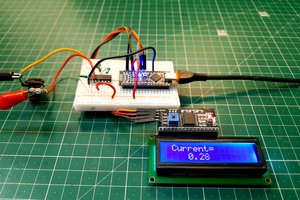
Close
0%
0%

Lucid Dream Helmet

Use an EoG+tACS controlled by an arduino to trigger lucid dreaming

egoego
Similar projects worth following
The lucid dream helmet concept is not a new one, and various people have used electro-oculogram devices to detect REM and trigger LED lights or alarms in the hope of initiating a lucid dreaming state. This is simply an expansion on the idea; a 40hz current applied by transcranial alternating current stimulation after dreaming is detected induces lucid dreaming in 77% of subjects. An arduino can be used as an EoG device by feeding amplified signal from electrodes placed near the eyes; while it does not have the computational power on its own to precisely determine eye movements, it should be capable of determining when a subject enters REM. From there I will first try using PWM output to simulate a 40 HZ AC current by controlling the output from an existing tDCS device I assembled to the same electrodes. If this does not work I will assemble a tACS device instead, or integrate it onto the same board as the amplifier.

This is my first Arduino project, so I'm using a SparkFun RedBoard (I'll worry about prettier form factors and portability once I have the basic operation down). 

/*The transcranial stimulator I made is a super cheap LM317 voltage regulator kit turned into a current regulator by slightly modifying the circuit and adding a trim pot; I'm not sure if I can use PWM to switch its output successfully, drive the electrodes directly from the redboard, or if I'll need to actually setup an oscillator of some sort. I have no formal training so a current regulated oscillator sounds a little daunting, however the 2ma current I'm using should make it unlikely that an oscillator would cause any sort of problem back at the arduino.*/

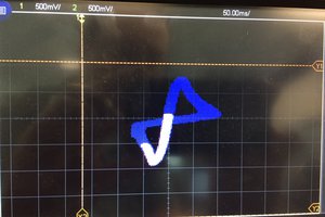
Scratch that, I'll use the arduino to generate a nice pretty sinewave at 40 Hz and just use a current limiter.

The EOG portion is on the surface, the trickiest part of this. Fortunately the folks at onloop.net have solved a huge part of this problem and I should be able to split their amplifier circuit in half, use 2 electrodes, and a much simpler program since I only care if REM is occurring, and not the actual direction of the eye movements.

Sorry there's no pictures yet; I'll try to draw up a diagram or something and take some purdy photos of the redboard and the existing tDCS unit.

  • 1 × ATmega 328 microcontroller ATmega 328 microcontroller
  • 1 × INA 118 instrumentation amplifier To make the signals more louder
  • 2 × LM358 OP Amp To be used as a notch filter and secondary amplifier
  • 1 × LM741 Amplifier and Linear ICs / Operational Amplifiers

  • Delays

    ego09/16/2014 at 15:10 0 comments

    Due to a medical issue in my family I haven't had time to work on this for a couple months. But that's about to change! Now I just need to run to frys to get assorted resistors/caps and we'll be in progress again.

  • The Output works

    ego06/28/2014 at 02:42 0 comments

    Well, that was fast. I got a nice pretty sine wave output from the board at a selectable frequency. Don't have a scope, but plugged it into some speakers and sure enough it sounds like a clean tone. Of course, I'm not sure it matters for this application. It makes the most sense to pump the same signal to 2 electrodes (the same ones used to detect eye movement) and use a 3rd as a reference, since I don't really have a simple way to supply true alternating current in a regulated matter. I'm pretty sure the brain has a frequency following response at least for a little while (long enough to "wake" the necessary functions),  so true alternating current shouldn't be necessary. Waiting for an extra set of lm317s to come in so I can test to see if current regulation wrecks the signal. I also just ordered the instrumentation amplifiers, but those won't come for almost a month (cheap from china, expensive and still slow from everywhere else).

View all 2 project logs

Enjoy this project?

Share

Discussions

J. R. wrote 08/04/2014 at 23:08 point
I am building almost the same device but going the "old school" route by creating an oscillator and a couple of timers. I also plan on trying the LM317 voltage regulator. I was thinking that if the device provides desired effect, I might have another go the arduino way.

  Are you sure? yes | no

Jared Harmer wrote 07/22/2014 at 01:05 point
I am interested in this project and I appreciate your good work.

I have begun working on this project with my dad, as I am very interested in lucid dreaming, but my experience with coding on Arduino is very limited and some help would be appreciated on how to change the output signal to 40 hz instead of the default 1000 hz in the code.

I have made an attempt to change the output to 40 hz, but the apparent output from the Redboard has been very inconsistent, and due to my limited experience in Arduino code, I am confused as to why this is happening.

Any suggestions? If you sent me the code that you are using that would be great, but if you added a short explanation, that would be even better.

Thanks in advance,
Jared

  Are you sure? yes | no

Similar Projects

Does this project spark your interest?

Become a member to follow this project and never miss any updates