Close
0%
0%

Hacking the Meccano M.A.X.

Meccano M.A.X. is a 30cm tall toy robot that is fun to build. This project aims to convert it into a machine vision robot.

Public Chat
Similar projects worth following
Meccano M.A.X. is a 30cm tall toy robot that is fun to build. Although there are mobile applications that allow you to control the robot remotely and provide rudimentary drag-and-drop programming capabilities, there is no open source Arduino libraries available to allow you to convert the toy robot into a robotic platform. The main objectives of this project is to change that and provide an Arduino library to control MAX and convert it into a machine vision robot,

This is an ambitious project in 3 phases:

  • Phase 1 - Create an Arduino library to control the MAX – this involves reverse engineering the Meccano protocol to communicate with the MAX smart components eg, locomotion, servos, facial expressions, etc.
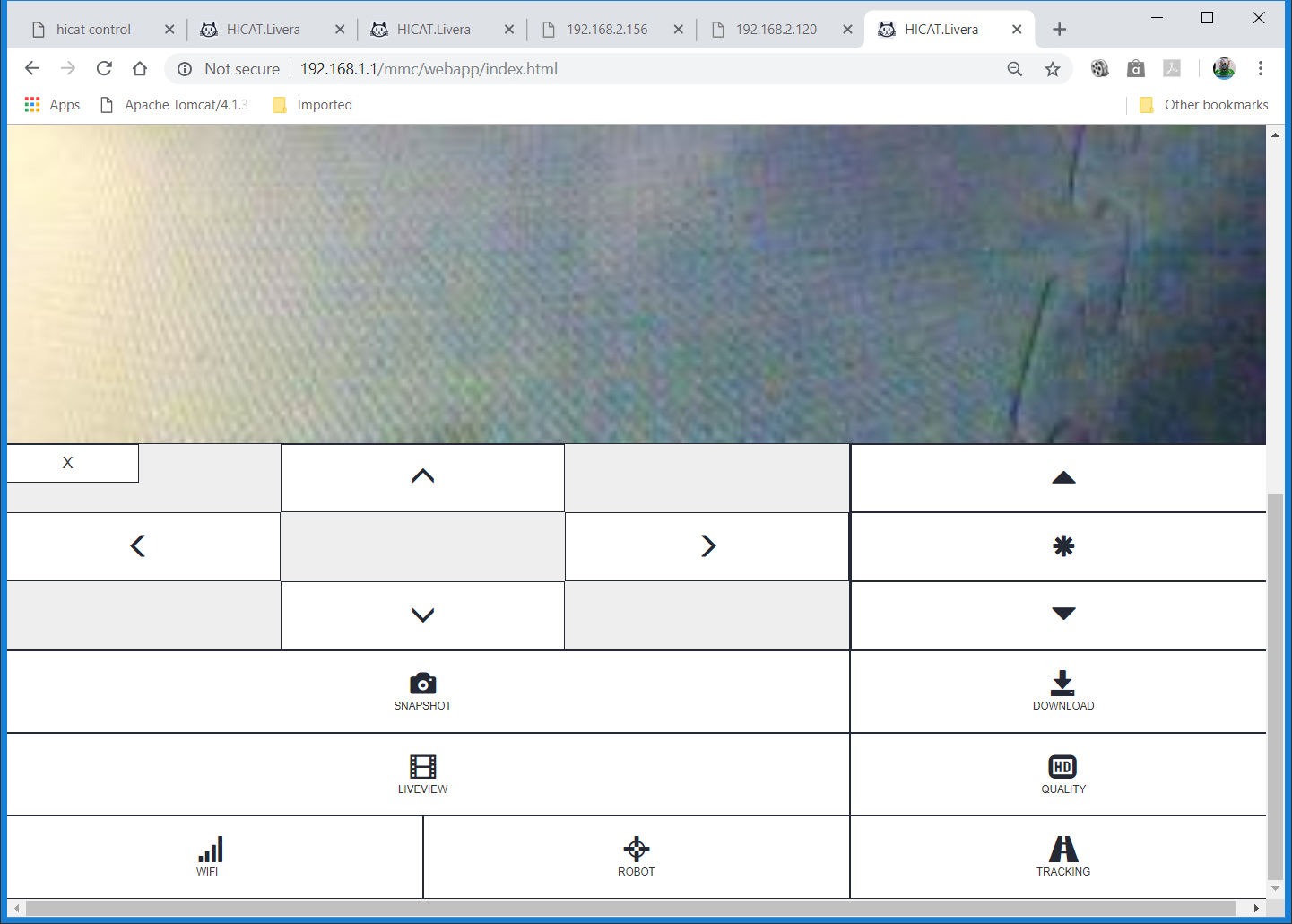
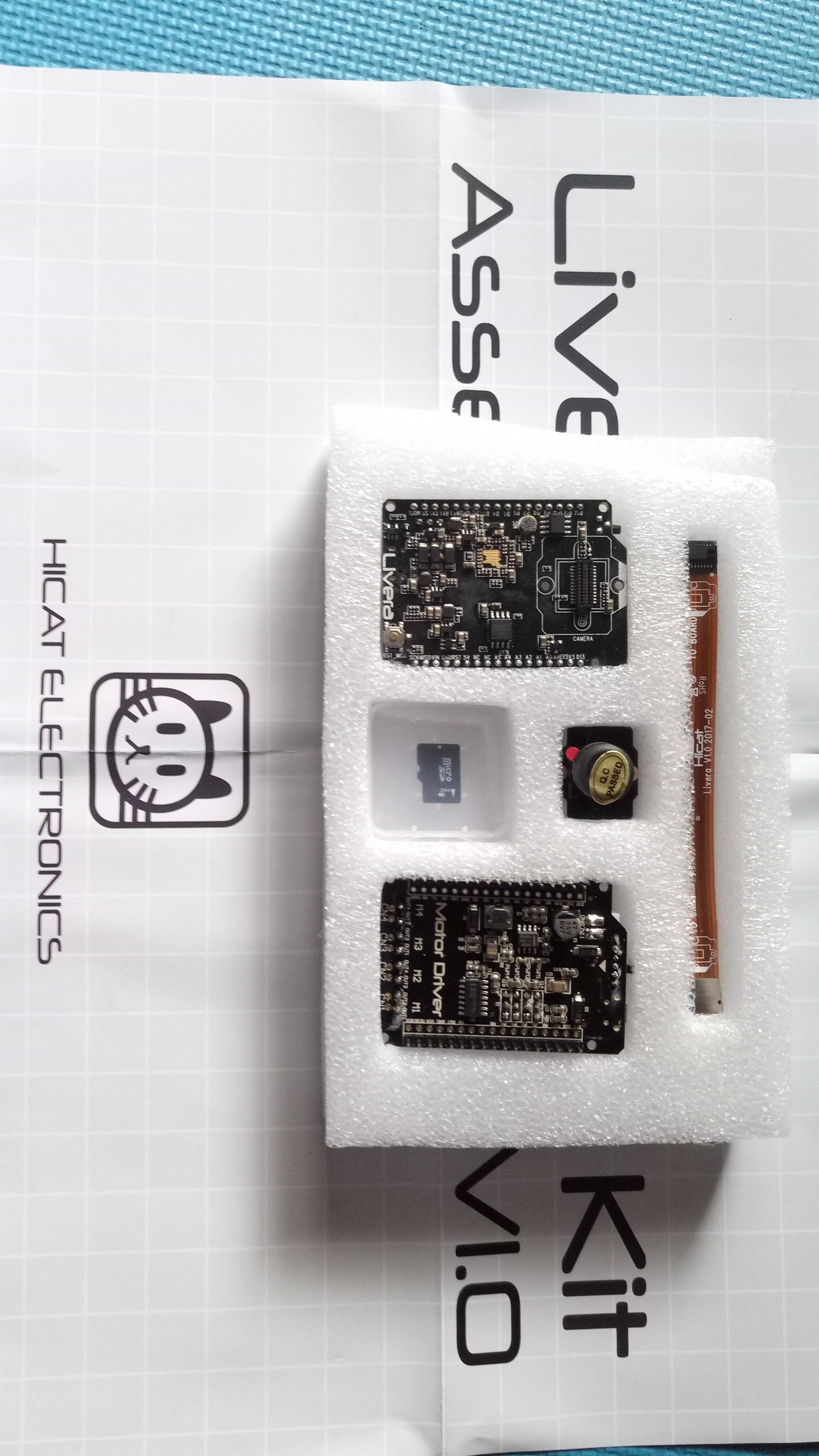
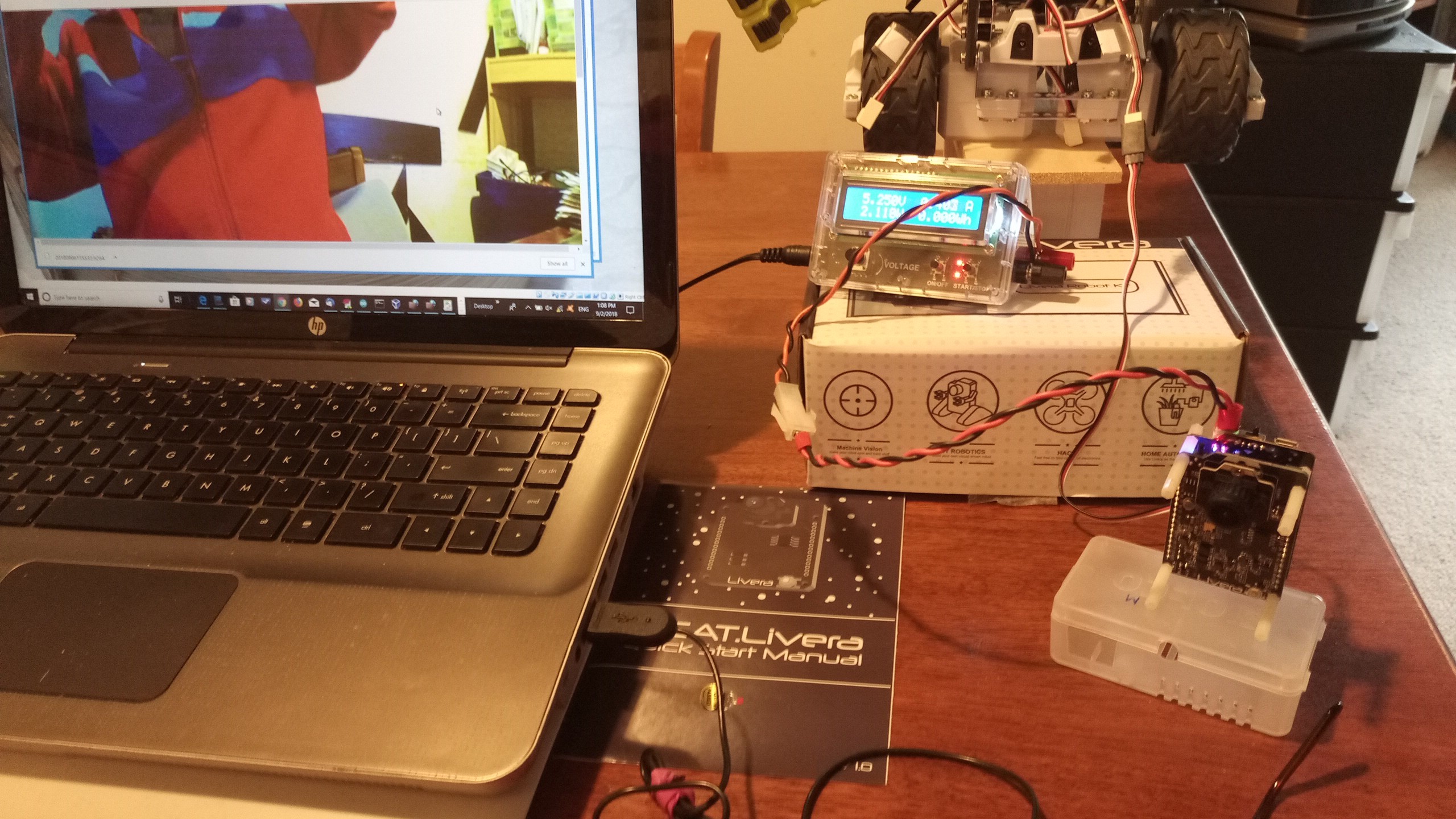
  • Phase 2 - Use HiCAT Livera to convert MAX into a Computer Vision-based robot – HiCAT Livera is an inexpensive machine vision platform for robotics. It consists of a camera, an embedded Linux platform with WIFI and a Arduino Leonardo compatible microcontroller in a small package. It is the latter that allows the use of the Arduino library developed in Phase 1 to perform low level control of the MAX.
  • Phase 3 - Control MAX from the Cloud – instead of controlling MAX using the HiCAT Livera embedded Linux, the video will be streamed to a container running machine vision/deep learning framework in the cloud.

MaxLivera.ino

Arduino Sketch for interfacing to the webapp running on the Hicat Livera board.

- 9.39 kB - 10/08/2018 at 22:16

Download

MaxClassDiagram.png

UML Class Diagram for the MeccaChannel Arduino Library

Portable Network Graphics (PNG) - 156.40 kB - 08/25/2018 at 04:32

Preview
Download

  • 1 × Meccano M.A.X. Robot Meccano M.A.X. is a 30cm tall toy robot being hacked into a robotic platform.
  • 1 × HiCAT Livera An open source machine vision platform with 720P video/photo capturing, WIFI, Arduino Leonardo compatible and an embedded Linux.
  • 1 × Livera Motor Driver It provides power, access to I/O pins on the Arduino Leonardo compatible as well as 4 motor drivers.

  • A Unusual MQTT, Kafka and Fuse Online IoT Demo involving Max

    MrDreamBot11/28/2018 at 23:12 0 comments

    Recently IBM bought Red Hat for $33 Billions mainly for its Openshift Container Platform. I created this demo using AMQ , Kafka, Fuse Online running on Openshift.  Max's movement is sent using MQTT and saved in a Kafka topic and then taken from the Kafka topic and saved in a file on a FTP site using Fuse Online integration. The file is then used as the source to playback the movements on Max using a small Java program.
    Enjoy ;-)

  • Apologies for the Truncated Video

    MrDreamBot10/09/2018 at 11:16 0 comments

    For some unknown reasons, the video has been truncated. I have deleted the truncated video and uploaded the complete version.

  • Controlling MAX using a webapp

    MrDreamBot10/08/2018 at 22:33 0 comments

    Here is a video showing MAX controlled by the webapp running on the Hicat Livera Camera Board:

    Yes, I finally got my second Hicat Livera board to replace the bricked one. I assembled the Livera with its motor driver board (used to provide 3A 5V power) and its pan-and-tilt unit (actually tile only) and used the assembly to replace MAX's controller (located in its mid-section). Before assembling them, I added 3 headers to the unused Arduino pins for controlling Meccano MAX's Locomotion, servo and Face. The pins are SCK, 12 and MISO respectively. See photo below.

    I modified the Hicat's robot Arduino sketch to use my Arduino library for the Meccano MAX so that Hicat's webapp can be used to control the MAX using a browser. The GUI is shown below.

    You can see that the live video is shown at the top while all the robot controls are below it.

    The video posted shows the use of the Hicat webapp to control the MAX including switching on a laser mounted on the tilt unit, driving back and forth, turning, while displaying the image captured on the camera. Unfortunately, the window showing the video is too big to see the whole live screen without scrolling up and down.

    The webapp is running on the embedded Linux of the Hicat Livera Camera board. It communicates with the onboard Arduino Leonardo compatible using Arduino's UART (Serial). Clicking the control widgets of the webapp sends a command to the Arduino which carries out the operations.

    The Arduino sketch "MaxLivera.ino" can be found in the repository on this page.

    The next step is to make MAX into a vision-based robot meaning that  it reacts to the environment by observing the change in scenery via the image fed by the camera.

  • ​A Quick Status Update: HiCat Livera Support Non-existent!

    MrDreamBot10/02/2018 at 21:15 0 comments

    A posted a question in Hicat Livera's forum asking how to unbrick the Livera 78 days ago but still no response. I noticed that the last activity in the Forum was back in May, not a good sign.  Then I noticed in Hicat's Youtube video: Livera Robot Kit Assembly Guide, another person was asking the same question I did 4 month's ago: "...changed the WiFi to connect to my router, now l cannot connect to it, and the reset sequence don’t work Any suggestions to fix it?...". And there was no response!


    I am getting another Livera to complete, at least,  this phase. I am also entertaining the idea of using a different platform for the project as it appears that Livera has been "retired" and there is no support. It does not make sense to move forward with this platform.

    Stay tuned!

  • My, oh my, I bricked my Hicat Livera!

    MrDreamBot09/23/2018 at 23:48 0 comments

    At last, I am back from my working holidays and getting back on the project. Before I went on holidays, I ran into an apparent power related issue where the laser was not switched on until a USB cable was also plugged into the Hicat Livera. The Hicat Motor Driver board specs says it can accept input voltage of 5-12V. I was using 5V input when I experienced the problem. I switched to use 12V and the problem goes away.

    I was eager to find out whether having sufficient power now will also allow the use of Wifi AD mode (Hicat's way of saying connecting to one's home wireless router) which I never got it to work before. I used the webapp to switch to AD mode. It did not work but according to my home router, it did get an IP address from it. I could not use the webapp or telnet to access it via the new IP address. When I ran into this problem previously, I could rely on the wifi reset RST-PCB switch to set it back to AP mode. This time I could not because the boot process appears to be having problem (red led on). I powered off and on many times without ever able to recover from it. In fact, the unsuccessful switching to AD mode bricked the Hicat Livera. So far, I was not able to unbrick it. I shall try again. The worst case is that I have to get a second Hicat Livera unit to continue with the project.

    If you've run into this Hicat problem before and were able to recover from it, please let me know how.

  • Phase 2: Interlude​

    MrDreamBot09/06/2018 at 02:41 0 comments

    Have to go away for 10 days on work/holiday: attending a conference overseas and taking a few days off. You won't be hearing from me during that time. Just want to let you know that I am not abandoning the project, just taking some time off due to work commitments.

    Did some testing yesterday loading the HiCAT robot sketch to test the laser. It was strange, when I was connecting to JiCAT's Leonardo using a USB cable, the laser worked. When detached, it did not work. Yes, the main power source was connected all the time. This appears to indicate a power issue. However, looking at the specs, the step-down converter TPS54329 has current out max at 3A! 

    Need to investigate further when I am back.

  • Phase 2 – First Encounter with HiCAT Livera

    MrDreamBot09/03/2018 at 05:39 1 comment

    You can find out more about HiCAT Livera here. I finally have all the components that I need to start Phase 2. The Livera and Motor Driver are shown below:

    The objective of this Phase is to convert the Meccano MAX into a vision-based robot using HiCAT Livera and its accompanying Motor Driver. Although the Meccano MAX already has motors for locomotion, the Motor Driver is a convenience board which provides voltage step down, servo connectors (which I am going to use for digital output to drive the 3 chains of MAX devices: motors, servos and Face. I am also going to use the Motor Driver’s motor capability to power a laser for effects.

    First thing first. I need 2 power cables to connect to the Meccano Max: one to connect to the battery another the other to a smart power supply which also measures the current used. I also need 3 servo cables to connect the Meccano Max’s devices to the Motor Driver’s servo connectors. These cables are shown in the following photo.

    The following photo shows the connection between the Livera/Motor Driver with a power source and the Meccano Max.

    When first powered up, the Livera comes up in what HiCAT calls the AP mode which is basically a hotspot at 192.168.1.1. I then pointed my browser at Livera’s webapp: http://192.168.1.1/mmc/webapp/index.html, changed to MJPEG mode and selected LiveView. You can see me on the computer screen. This is all the success I am getting so far. I had no luck trying the other features of the webapp:

    • Changing the WIFI to AD mode (HiCAT's term for connecting Livera to your own router the AD mode) – I did that. It gets an IP address from my router (seen on the router) but webapp no longer responds to any request: webapp or telnet anymore. Resetting to AP mode works but I still can’t connect it to my router and access it using my PC connected to the same network.

    • Changing to Robot mode – nothing happens. Yes, I’ve replaced the Arduino sketch for the HiCAT robot with my sketch for the Meccano Max. I even added the Laser. No luck. I shall try HiCAT’s sketch later to see if I can, at least, get the laser working. If it does, it means that the problem is with my sketch otherwise it is a Livera problem.

    This is as far as I get with a quick test drive of Livera/Motor Driver. I need to spend more time RTFM.

  • Completion of Phase 1

    MrDreamBot08/25/2018 at 04:49 0 comments

    I have published my MeccaChannel Arduino library to Github and included a UML class diagram to make it easy to understand. There are a couple of unsupported features:

    1. Learned Intelligent Movement (L.I.M.) programming which allows you to create and record animations by physically moving the robot
    2. Meccano M.A.X.'s Infra-red Distance Sensor (Class provided but not yet working)

    Although the support for Meccano M.A.X. devices is incomplete. They are sufficient for me to move on to the next phase as I shall be using computer vision instead of an IR sensor for navigation in Phase 2. But this does not mean I am not going to add the missing features later.

    If you are reading the source code, you should note that I am using GOF's Chain of Responsibility Design Pattern to loose-couple MeccaChannel with the M.A.X. devices. MeccaChannel implements the Meccano Smart Protocol with extension for the M.A.X. motors and Face. Each MeccaChannel will require an Arduino digital pin and supports up to 4 devices. 

    On the M.A.X., the 4 channels are used for:

    • Channel 0: left and right motors for locomation
    • Channel 1: Servos for head and claw movements
    • Channel 2: Face
    • Channel 3: IR distance sensor

    In Phase to, I am going to use the HiCAT Livera camera and motor driver (mainly for power supply and easy connection to the channels instead of using its 4 inbuilt motor drivers). The Arduino library will be running on hiCAT Livera's Arduino Leonardo comptible and the camera will be managed by Livera's embedded Linux. Livera also has built-in WIFI and a web server. Stay tuned for my next update.

  • Objectives and Components

    MrDreamBot08/20/2018 at 09:22 0 comments

    This is an ambitious project in 3 phases:

    1. Create an Arduino library to control the MAX – this involves reverse engineering the Meccano protocol to communicate with the MAX smart components eg, locomotion, servos, facial expressions, etc.

    2. Use HiCAT Livera to convert MAX into a Computer Vision-based robot – HiCAT Livera is an inexpensive machine vision platform for robotics. It consists of a camera, an embedded Linux platform and a Arduino Leonardo compatible microcontroller in a small package. It is the latter that allows the use of the Arduino library developed in Phase 1 to perform low level control of the MAX.

    3. Control MAX from the Cloud – instead of controlling MAX using the HiCAT Livera embedded Linux, the video to streamed to a container running machine vision/deep learning framework in the cloud.

    Components

    The components used in each phase are listed below:

    Phase 1:

    • A Meccano MAX Robot

    • An Arduino UNO (could be replaced by the HiCAT Livera, I started the project using a UNO)

    • A 5V power supply (or the rechargeable battery that comes with MAX)

    • Some jumper wires

    Phase 2:

    • A Meccano MAX Robot

    • A HiCAT Livera board

    • A Livera Motor Driver

    • Power onnector

    • Some jumper wires

    Phase 3:

    • Everything in Phase 2

    • A private cloud built using Red Hat Openshift running on a notebook

    Phase 1

    Although the Meccano site provides a Smart Module Protocols document, an Arduino library and an example project, they are all out-of-date and usable only versions of the Meccano Meccanoid Robots. To use the MAX’s components such as the motors, face LED screen, etc., the extended protocol has to be reverse engineered. I started my collaboration with “bmd1103” on the Arduino Forum some time ago on the subject. The reverse engineered information, although by no means complete, is in a usable state to control the MAX.

    The Meccano protocol is a weird one. It uses an async like protocol with start/stop bit and a high and low to represent 1 and 0 in one place and long/short pulse width to represent 1 and 0 elsewhere. And the check sum is calculated differently depending on the device!

    The video shows an Arduino UNO controlling the motors, servos (head and claw) and the face expression virtually at the same time.

View all 9 project logs

Enjoy this project?

Share

Discussions

Bill Burnard wrote 07/19/2021 at 01:55 point

How did you get the LED matrix to run custom text?

  Are you sure? yes | no

cmarinv2005 wrote 05/11/2019 at 17:59 point

Perfect, I would like to be able to place a camera on my MAX robot ..

  Are you sure? yes | no

Similar Projects

Does this project spark your interest?

Become a member to follow this project and never miss any updates