 David Prutchi
EmotiGlass
By: David Prutchi and Jason Meyers
IMPORTANT NOTE: A complete, single-document whitepaper for the project is available for download at: https://cdn.hackaday.io/files/1606156871752160/EmotiGlass%20-%20v4.1%20PUBLISHED%20-%20.pdf
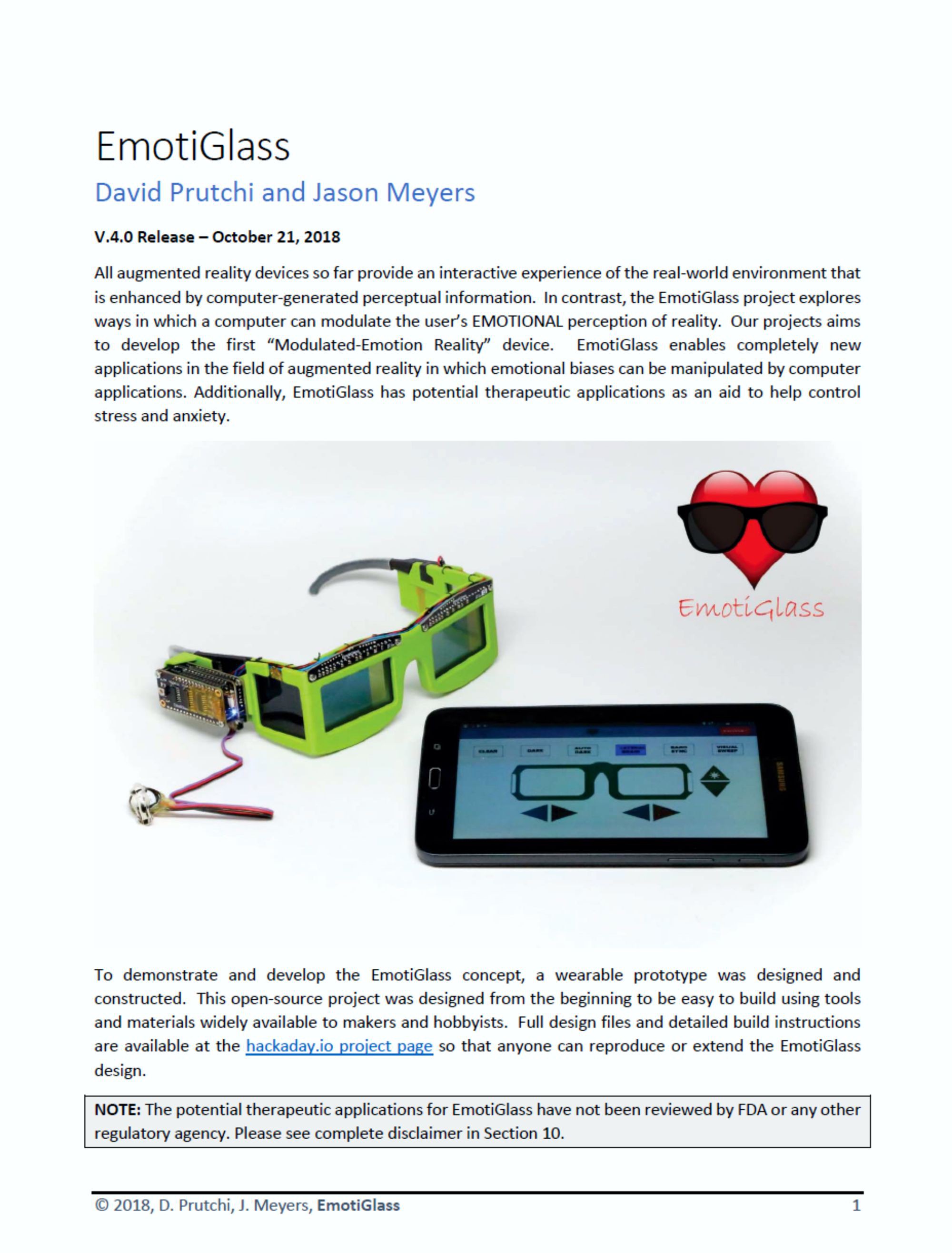
All augmented reality devices so far provide an interactive experience of the real-world environment that is enhanced by computer-generated perceptual information. In contrast, the EmotiGlass project explores ways in which a computer can modulate the user’s EMOTIONAL perception of reality. Our projects aims to develop the first “Modulated-Emotion Reality” device. EmotiGlass enables completely new applications in the field of augmented reality in which emotional biases can be manipulated by computer applications. Additionally, EmotiGlass has therapeutic applications as an aid to help control stress and anxiety.
Background
Does the sight of a dog make you happy or fearful? Are you comfortable around people of other races? We commonly think that the emotions aroused by events around us are the results of our biases and prior experiences. This is very true, but there is much more than meets the eye when it comes to understanding the way in which our brains attach emotional content to our perceptions.
We develop implantable cardiac medical devices for a living, and a few months ago, we came across an interesting journal article that caught our curiosity. In this paper [Azevedo, et al. 2017], researchers from the University of London and their colleagues showed that presenting an image at different periods of the cardiac cycle would cause changes in the way that subjects would emotionally perceive that image.
The paper reported that racial biases could clearly be modulated by changing the timing at which an image is presented. In this study, pictures of dark-skinned or light-skinned individuals holding various objects were presented to coincide with either the heart’s contraction (cardiac systole) or relaxation (diastole). Results showed that if the image was presented during cardiac systole, subjects significantly misidentified innocuous objects as weapons when they were held by dark-skinned people. Remarkable!
A group from University College London conducted a related study [Gray, et al., 2009] through which they found that sensory processing depends on when stimuli are experienced in relation to heartbeat timing. Specifically, the perception of pain – which is strongly biased by emotion—varied depending on when during the cardiac cycle noxious stimuli were delivered to the subjects.
The mechanism behind these effects seems to be that the emotional arousal caused by a stimulus depends on signals being received by the brain from the body’s internal blood pressure sensors (baroreceptors). Simply timing the delivery of stimuli against the cardiac cycle can change the way in which the brain processes stimuli!
It’s not only the timing component of a stimulus that can change the emotions that it arouses. The spatial component also has major effects on the emotional perception of visual scenes. In his exciting book “Of Two Minds: The Revolutionary Science of Dual-Brain Psychology”, Dr. Fredric Schiffer [1998], a Professor of Psychiatry at Harvard Medical School and Attending Psychiatrist at McLean Hospital, showed that very distinct emotions can be evoked by selectively blocking access of the visual field to one of the brain’s hemispheres.
Spatio-temporal changes in the visual field also cause deep changes in emotional response. EMDR (Eye Movement Desensitization and Reprocessing) is a known psychotherapy technique whereby causing side-to-side eye movements is believed to unlock a memory mechanism that can be used to reprocess traumatic events. Outside the therapeutic setting, mild side-to-side...
Read more »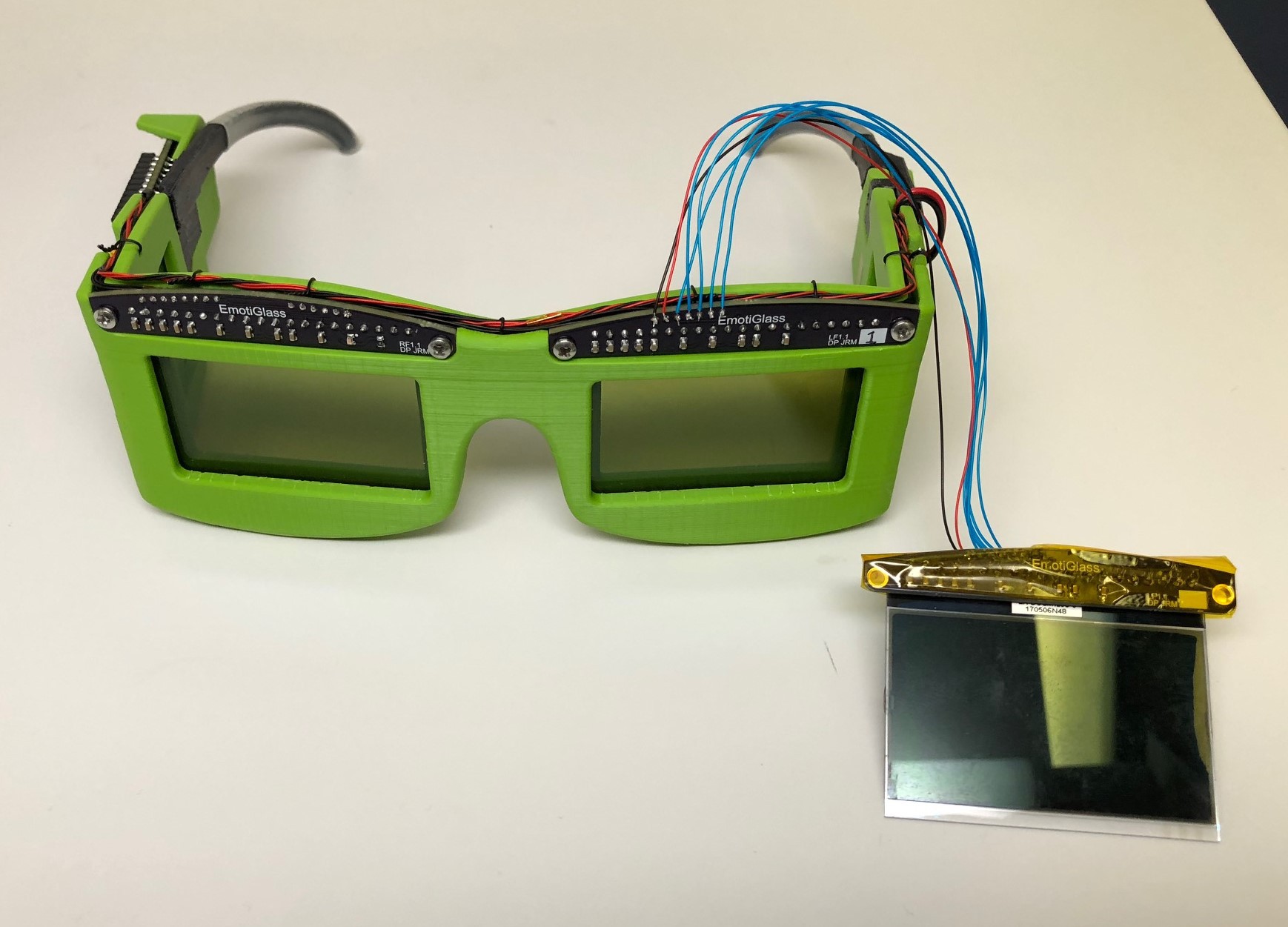
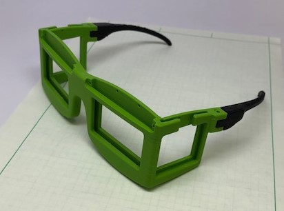
 A second copy of the wearable prototype has been completed. The build for this prototype was documented and photographed so that we could provide easy to follow build instructions. The build instructions document has been uploaded.
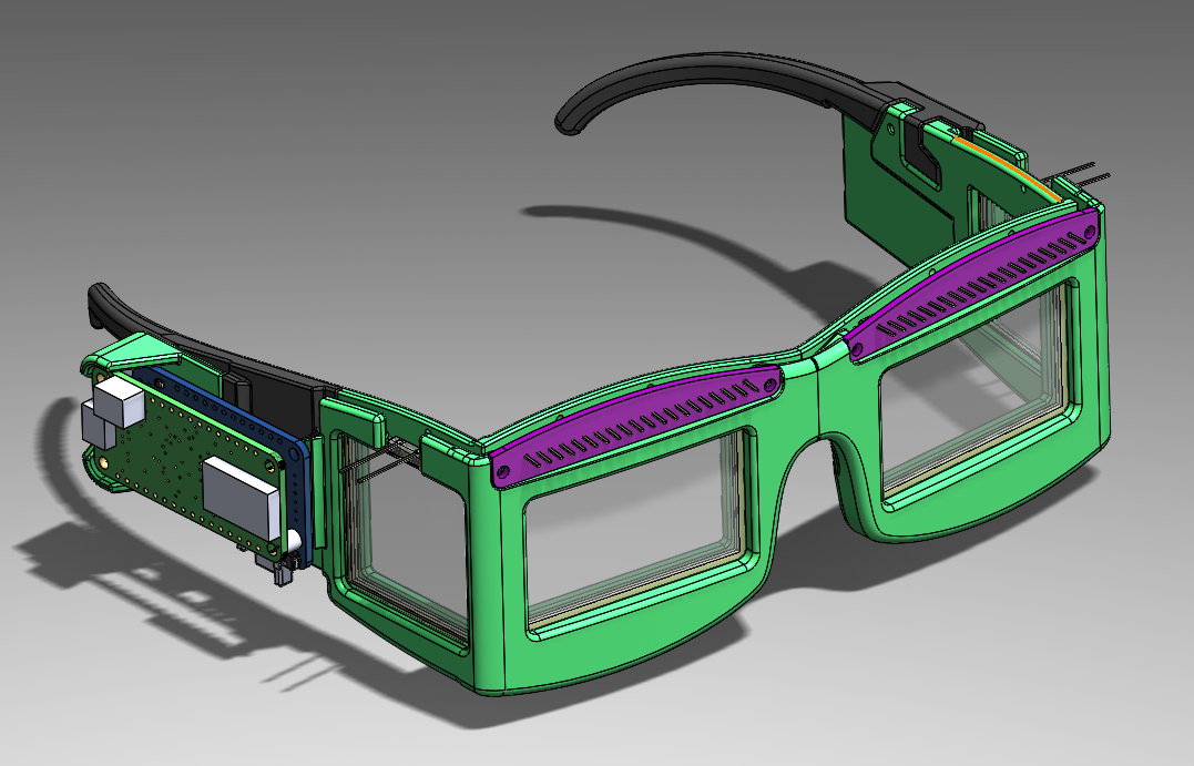
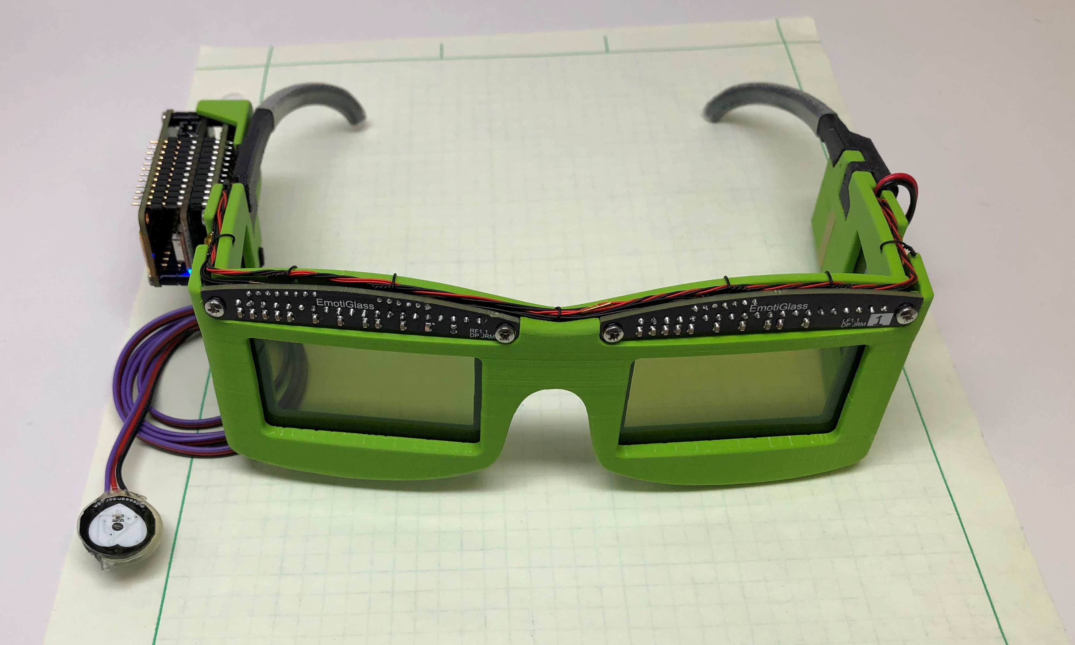 We are very excited to post that the first wearable prototype of EmotiGlass is now complete. We have confirmed that the device powers on and accepts commands via bluetooth, and that all operating modes are functional.
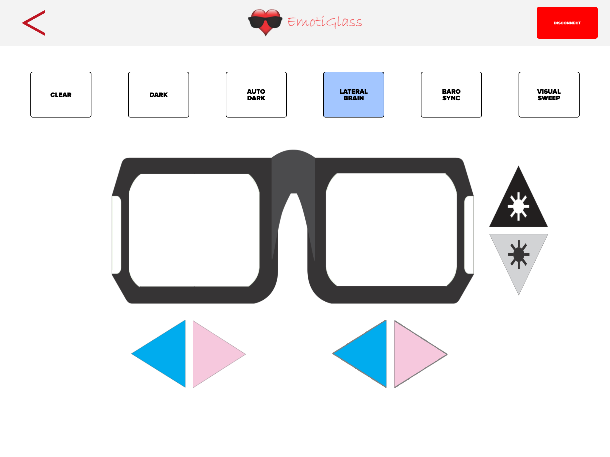
 Xasin
Xasin
 Casual Cyborg

 Andrei Speridião