The CAD model for the wearable prototype has progressed, and a first rev of the main frame piece has been printed. The frame is being designed with the front and 2 sides as separate parts. This allows the front piece which holds the glass LCD displays and shutters to be printed from a stiff plastic (PLA for now, but I may eventually switch to a CPE family material so I don't have to worry about leaving the print in a hot car), allowing it to provide the most protection possible to the glass. At the same time, the sides can be printed from a more flexible material from the Nylon family, which will allow the Emotiglass prototype to fit on heads of different sizes (hopefully) without being uncomfortable.

As soon as I completed the model for the front frame piece, I wanted to print it because I was expecting to need to make some adjustments to the fit. This part takes about 11 hours using a .4mm nozzle in an Ultimaker 2+. Sticking to this smaller sized nozzle makes it possible to remove the support material without too much hassle. After clearing the support and a few minutes of filing, I was able to test the fit of the components:
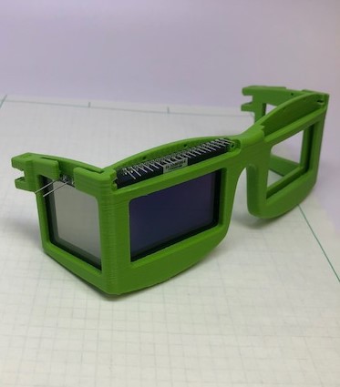
The fit on the display and shutter came out very well for a first test, needing adjustments of less than a millimeter. The fit on a face, on the other hand, wasn't as good. We tried holding the part on a few different faces, and concluded that the bridge needed to move down significantly. Additionally, I've flattened out the area above the bridge in the hopes that that may improve comport:
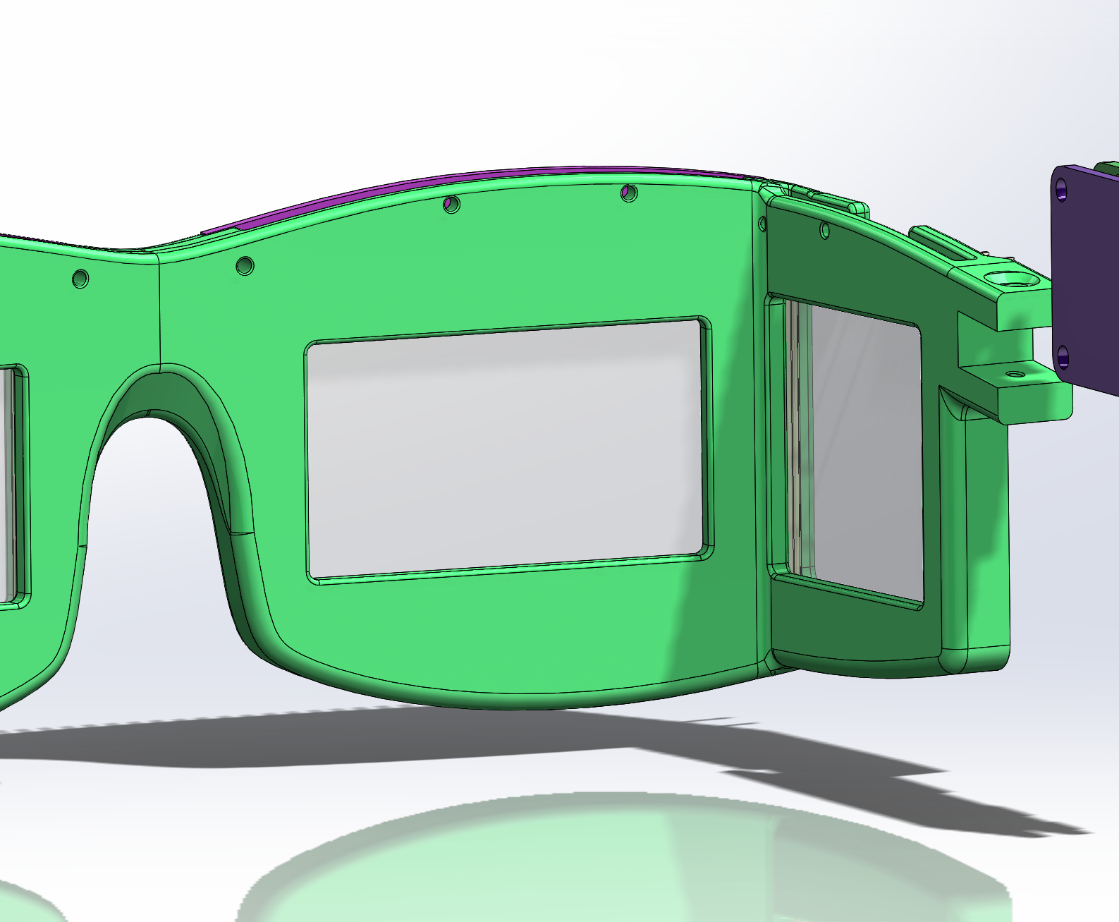
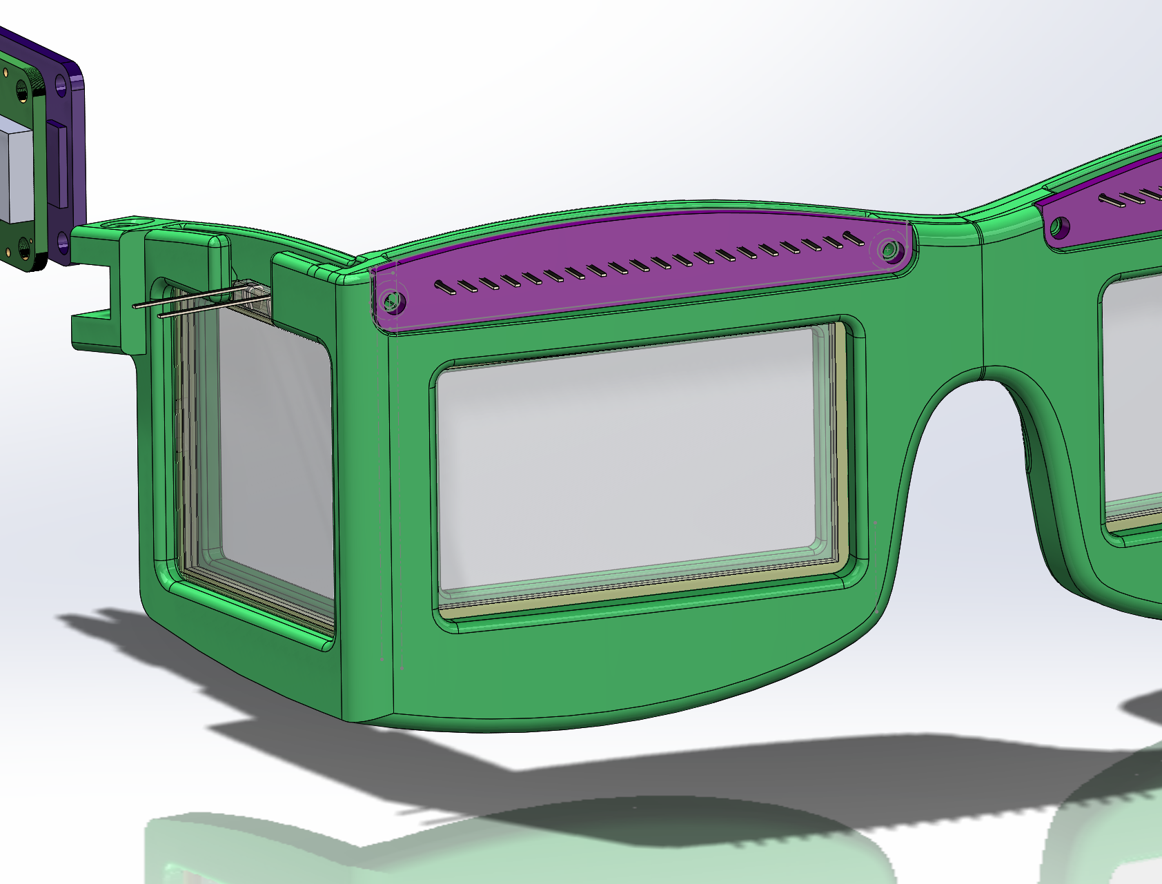
As the second rev prints, focus shifts back to the PCB layouts. The initial outlines are transferred from this model into Altium for PCB layout to see how everything fits. There is room to extend the PCBs downward somewhat, so they'll be adjusted as needed. The PCB shapes are shown in purple in the following image. 2 screws (not shown in the model) will secure the boards. The holes are sized to support either imperial or metric hardware - a #2x1/4" or M2x6. The holes are sized for standard (cheap) machine or sheet metal screws.
With the front cad close to done, focus will shift back to the electronics. I'll swing back to the cad model and finish the sides after the boards are ordered.
Discussions
Become a Hackaday.io Member
Create an account to leave a comment. Already have an account? Log In.