 Matthew James Bellafaire
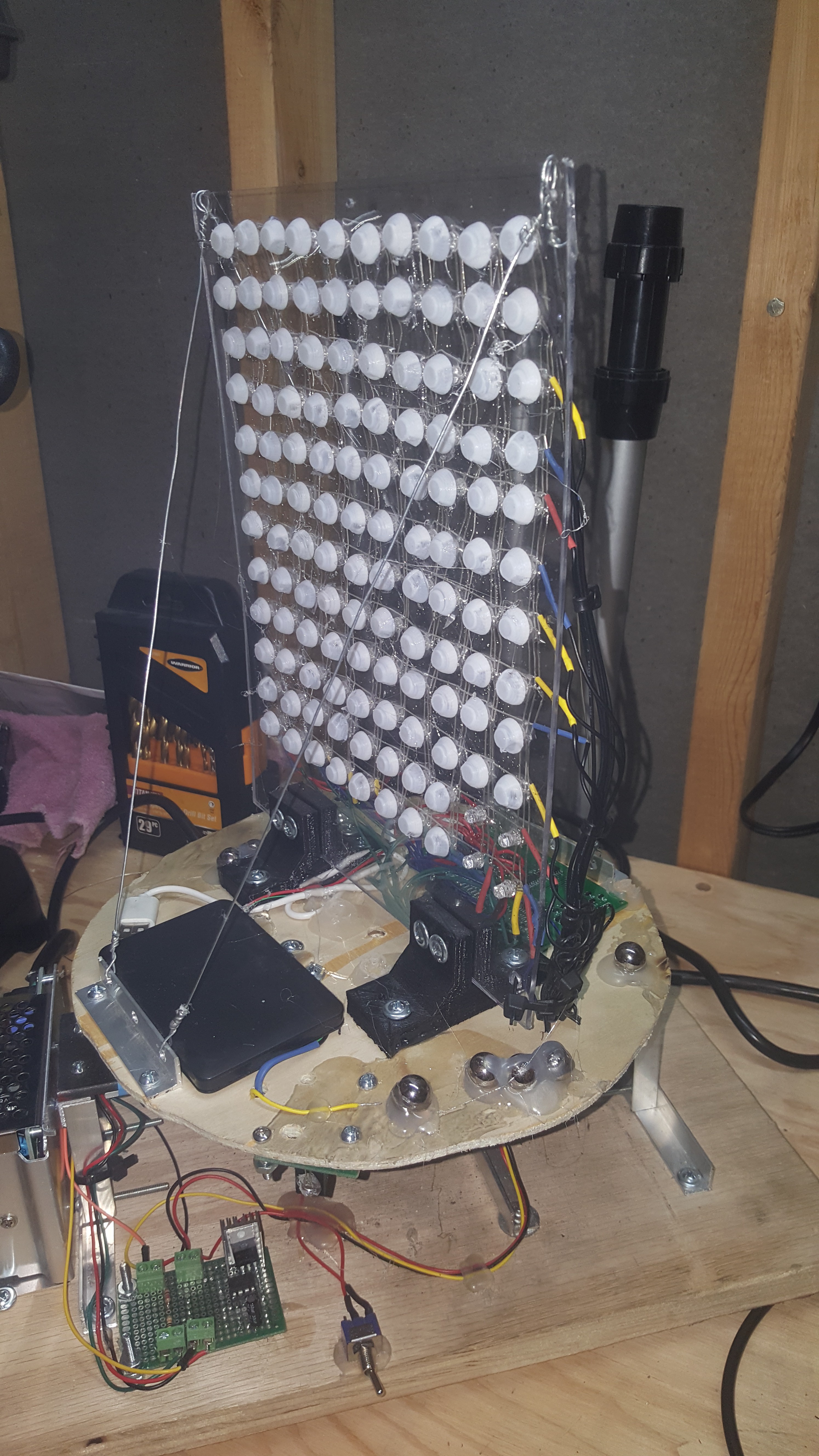
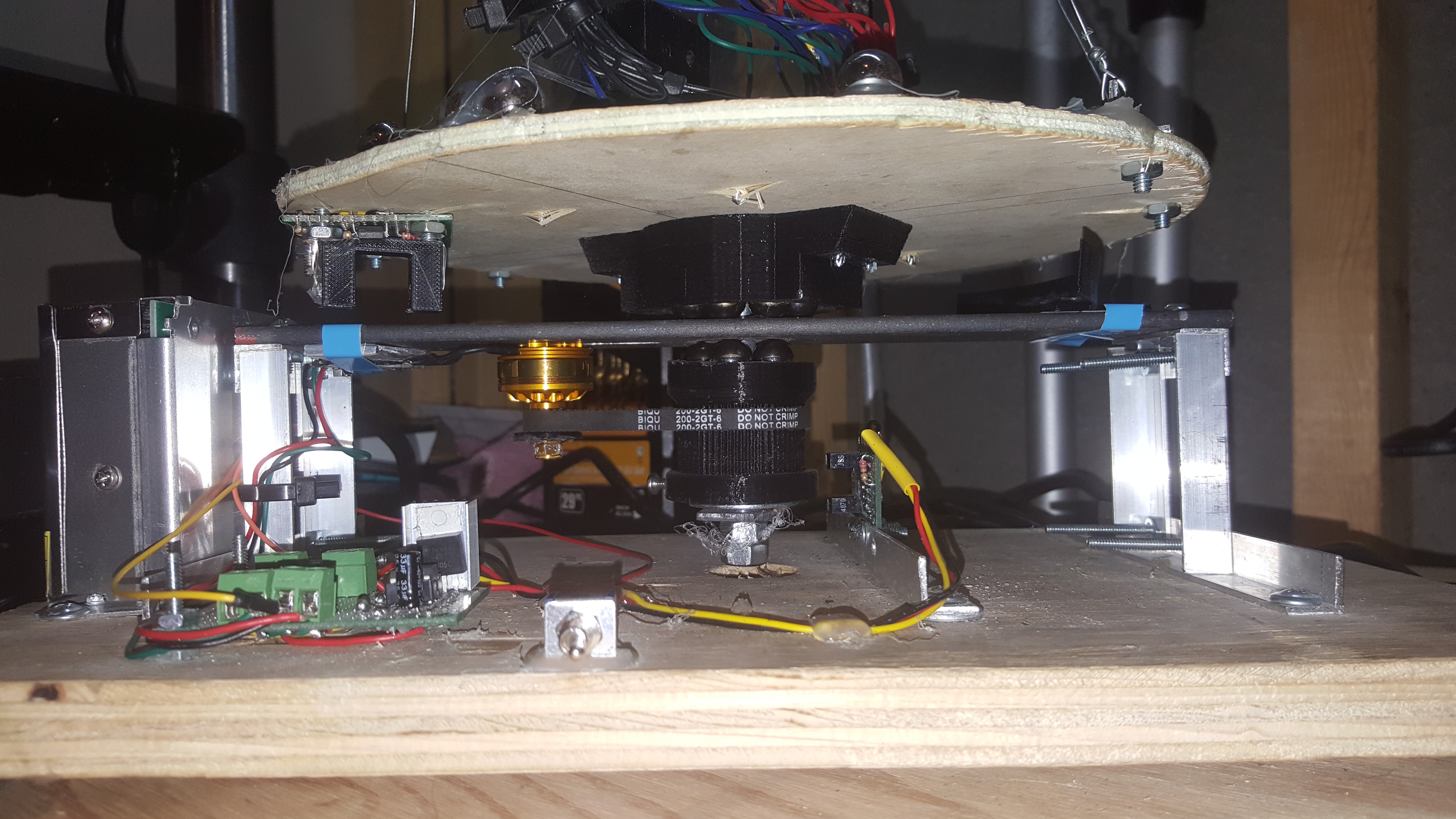
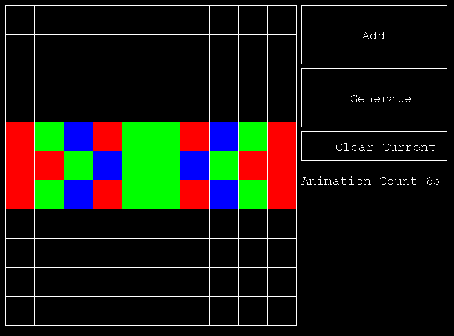
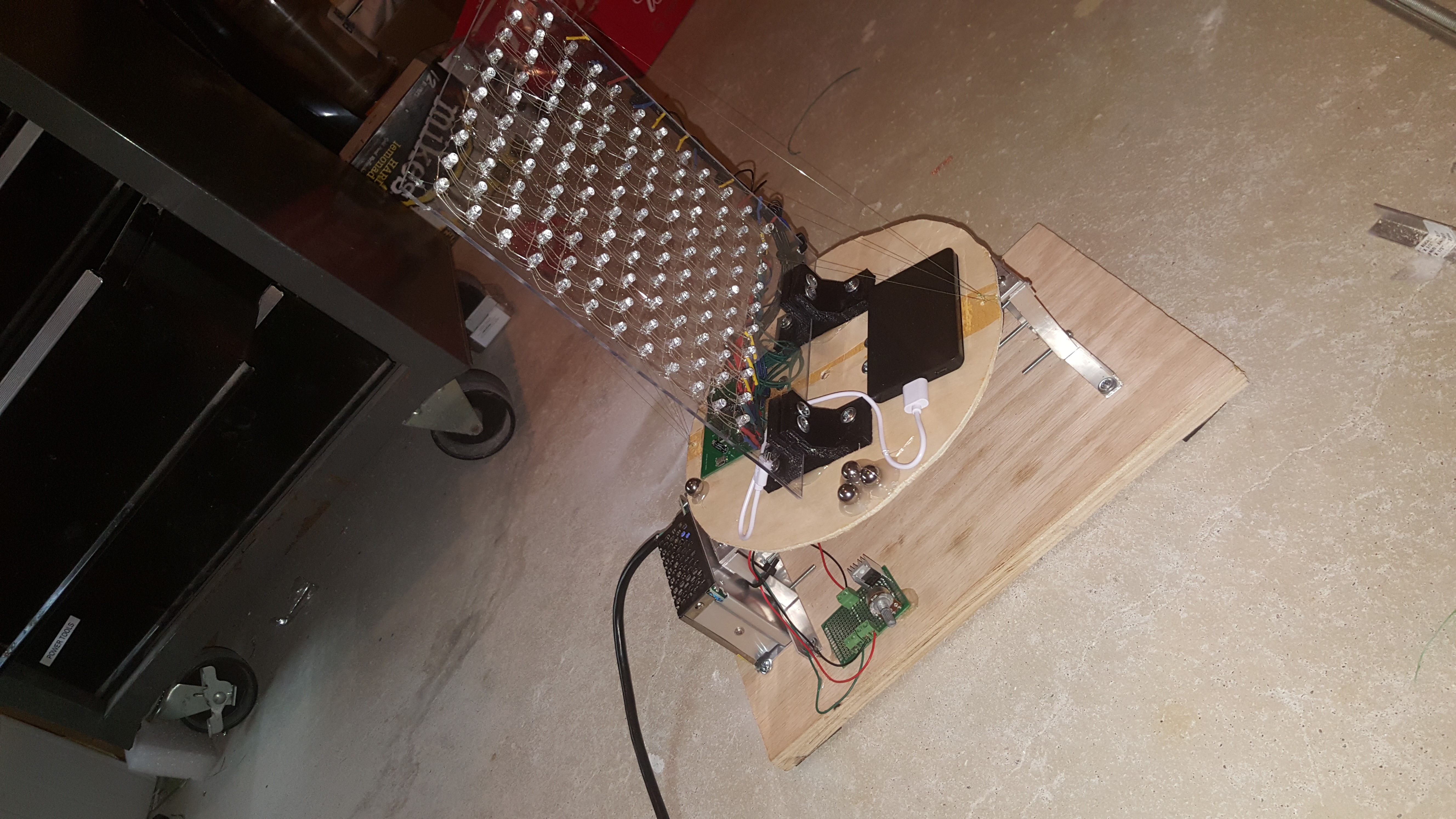
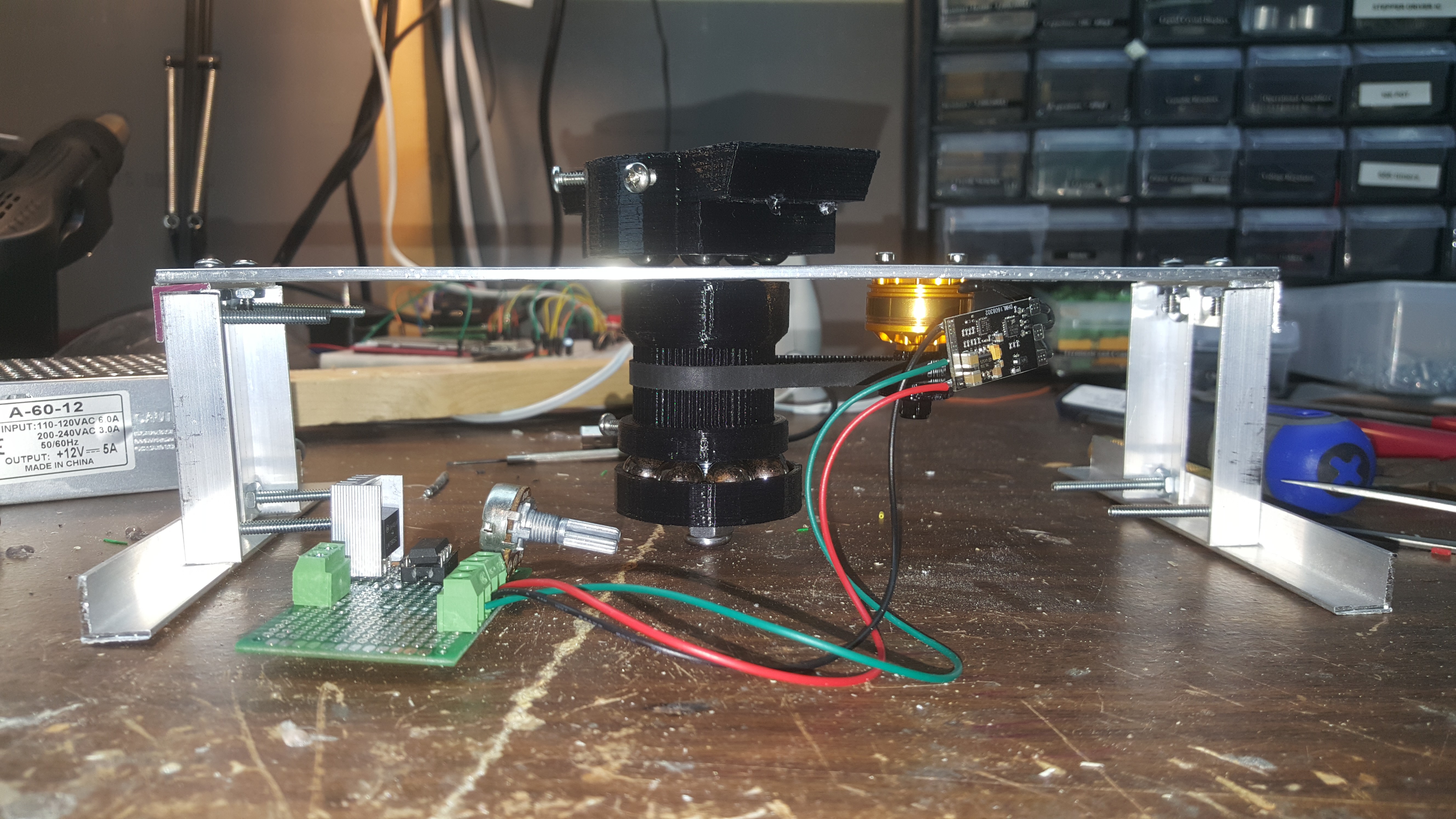
This is one of the most demanding projects I've ever taken on, it began around the end of august and was finished towards the beginning of march. The goal was to create a LED matrix display which would be rotated quickly enough to generate a 3D image. There was no shortage of problems to overcome on this project. Here's the final project video:
Check out the project logs to see the building of this project from the beginning!


 Peter Walsh
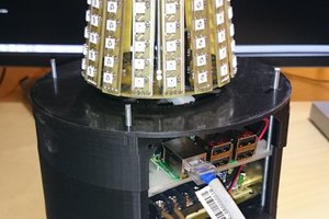
 SUF
SUF
 Viva Penguinos
I like this idea! Rather than turning the large plexiglass plate and base, did you consider using a much lighter main shaft and wire cross member design to support the LEDs? I think it would be easier to rotate it faster and with less wobble.