 Matthew James Bellafaire
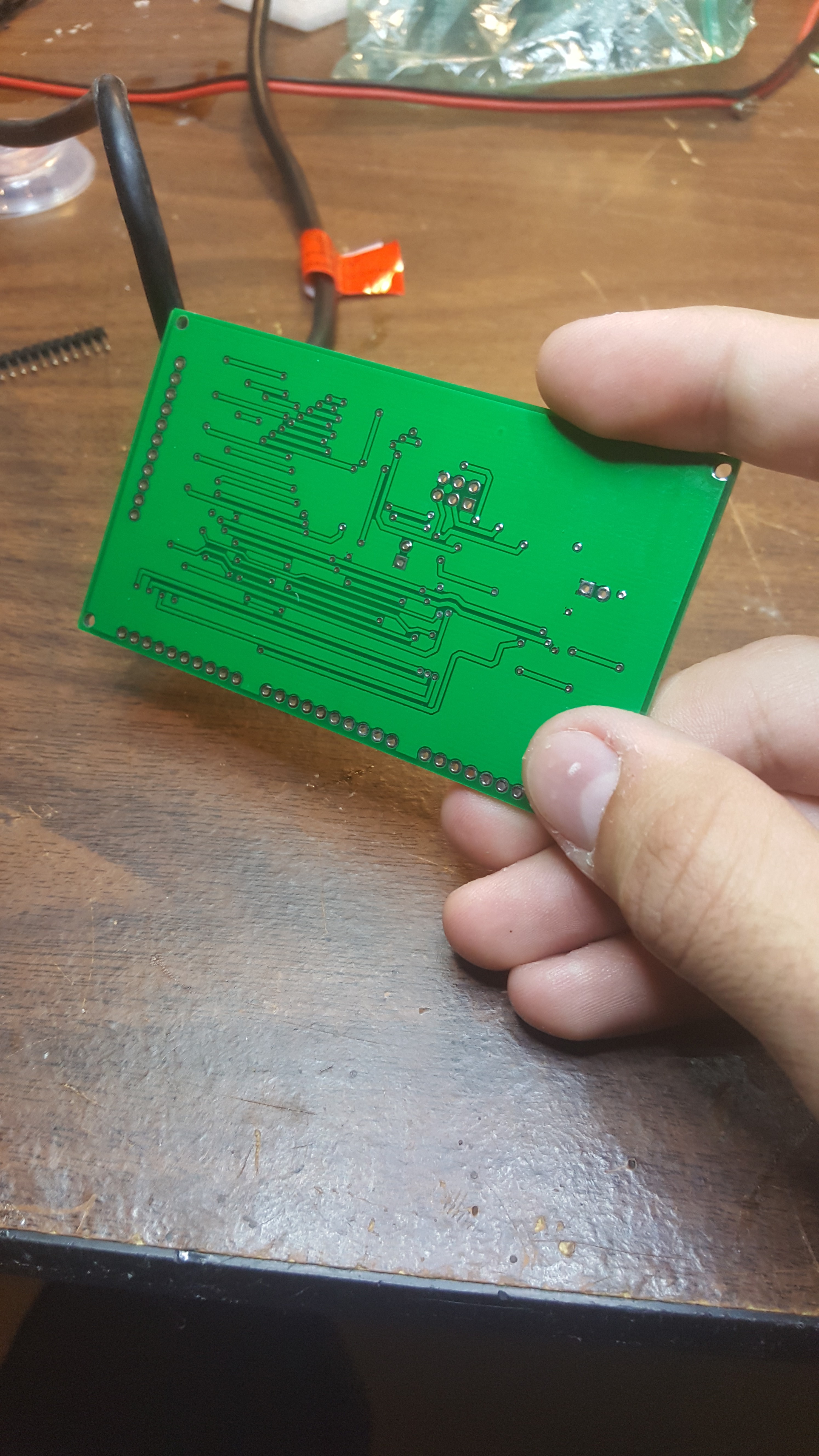
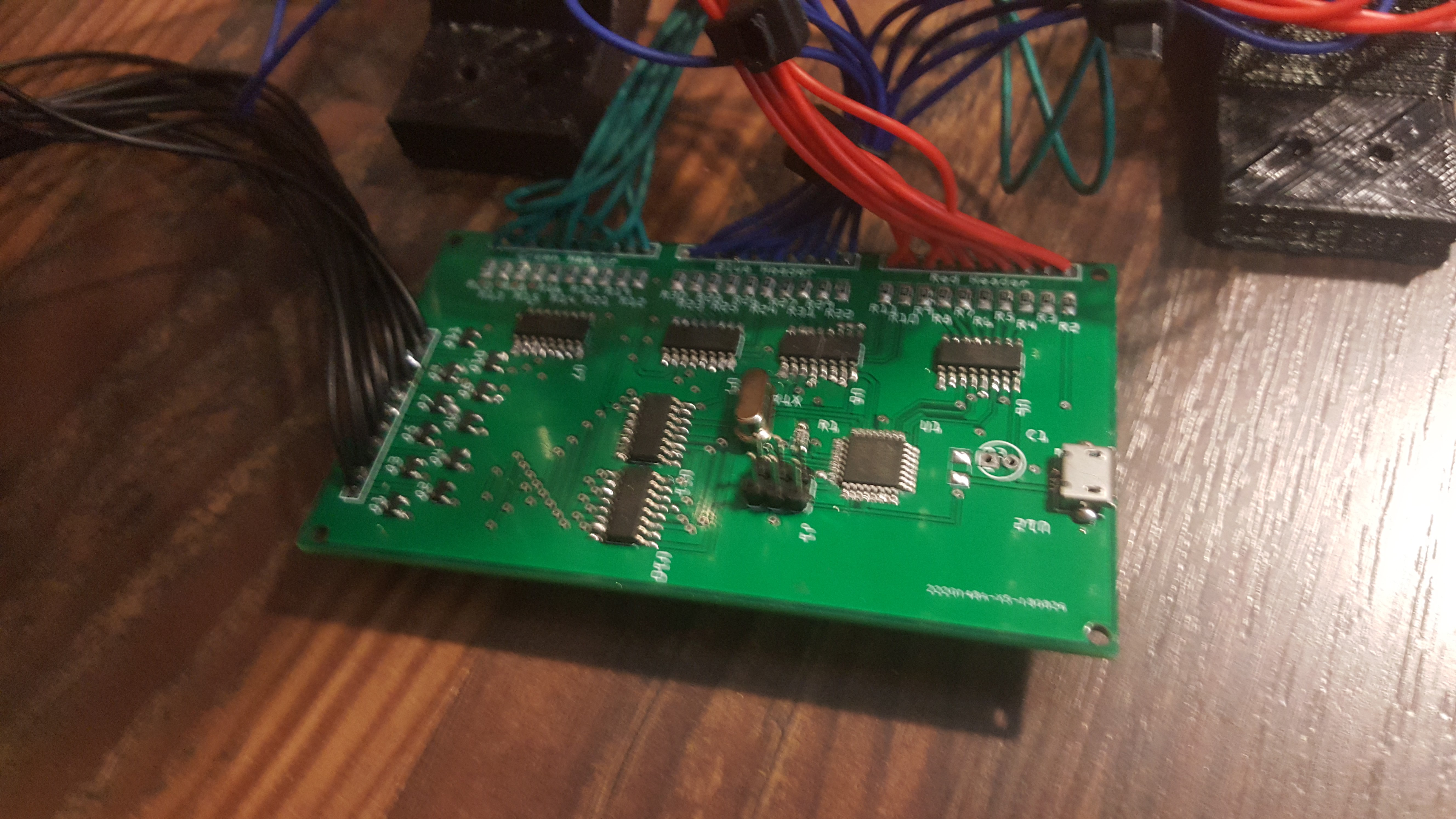
First off, i got the boards in hand and all the parts which was assembled last week. Everything looks great on them:
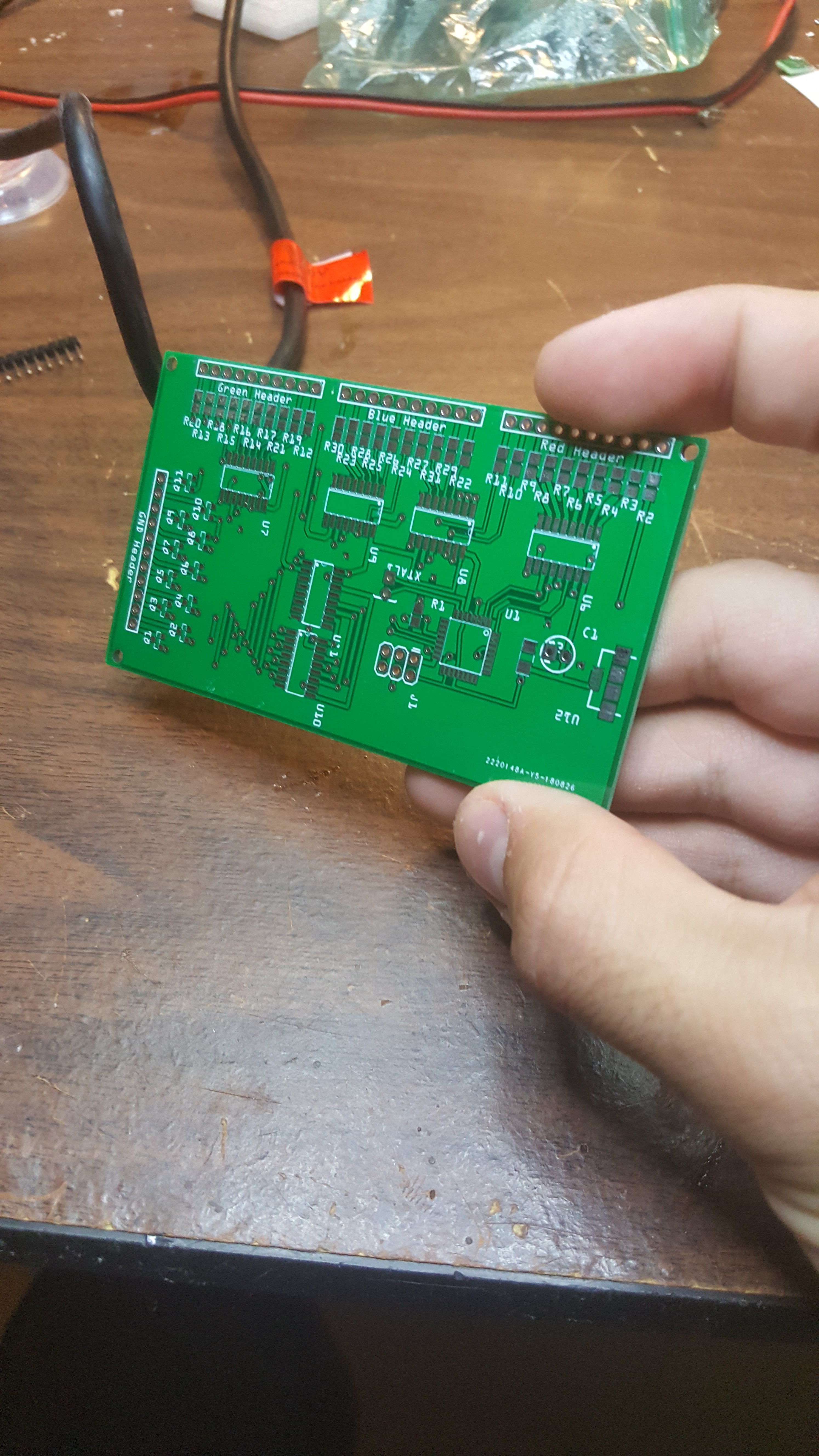
but when in originally went to go try to use the board well (as i would expect when things are going well) they didn't work. after a few hours of troubleshooting i discovered the issue. for whatever reason the atmega328 in a TQFP-32 package has a different device signature than the atmega328 in a DIP-28 Package. Which in all honesty makes sense, the TQFP has 2 extra IO pins, which could cause issues if someone were to upload a sketch that was originally for a different Atmega.
of course though, knowing what the issue is and how to fix the issue are two different things, spending some time browsing similar issues on various forums told me roughly what i had to do but nobody had encountered the exact same issue as me, the solution to getting a non-zero device signature in the arduinio IDE is more or less to modify the avrdude configuration file and just change the signature to whatever the chip you're using is. Fantastic, put that in and got a sketch to upload, the rest should be easy sailing right? i wish.
now the program could be uploaded through the ICSP header with a few little quirks. but the programming began. at first it was a straight forward attack strategy: start by using the digitalWrite to manually control the shift registers to get the desired pattern, after figuring out how it all works go with and try to make more complex patterns, then finally create some generalized functions that are easy to utilize to do whatever.
I ran into issues on the second part of that attack plan, i could get a pattern but not reliably. Regardless i stuck with it trying to work my way down to make more and more stable functions to handle different levels of the program. one of the major issues here was that the digitalWrite function wasn't nearly fast enough to deal with the shift registers, compounding issues further modifying registers directly in one go (PORTB = B10000010) seemed to cause the registers to do some weird things before finally putting power on the pins which messed with the shift registers. Finally changing the values directly utilizing the PORTB |= _BV(PD0); command solved almost all my issues and made the circuit function properly and allowed me to get the data out to the shift register correctly with very few issues.
aside from that the method that was used to display images in this project goes something like this:
- take 110 item byte array (0, 1, 2,3 represent color)
- taking the row count variable cut out the row we are working with and split into three color byte arrays
- feed those arrays into the shift registers to be displayed
- shift the high signal in the low-side shift register by one
- repeat.
the advantage to using the array to "draw" my images is that it's fairly easy now to add more images, just define them as a const byte to save on dynamic memory and set the array being displayed equal to it at will.
all and all, getting this thing working took me most of my weekend on-and-off and again. But if there wasn't going to be a challenge then this project wouldn't have been worth attempting.
unfortunately i don't have any images of this project working as i'm writing this so they'll be in the next project log.
Discussions
Become a Hackaday.io Member
Create an account to leave a comment. Already have an account? Log In.