 Matthew James Bellafaire
I don’t think I can say this enough, I’m a computer engineering student currently and mechanical design has never been a strong suit for me. With that said, I for some reason decided to design every part of the mechanical system myself (including the bearings). Hindsight is 20/20 on this one and I don’t think I’ll attempt the same thing without thoroughly thinking it through first but here we go.
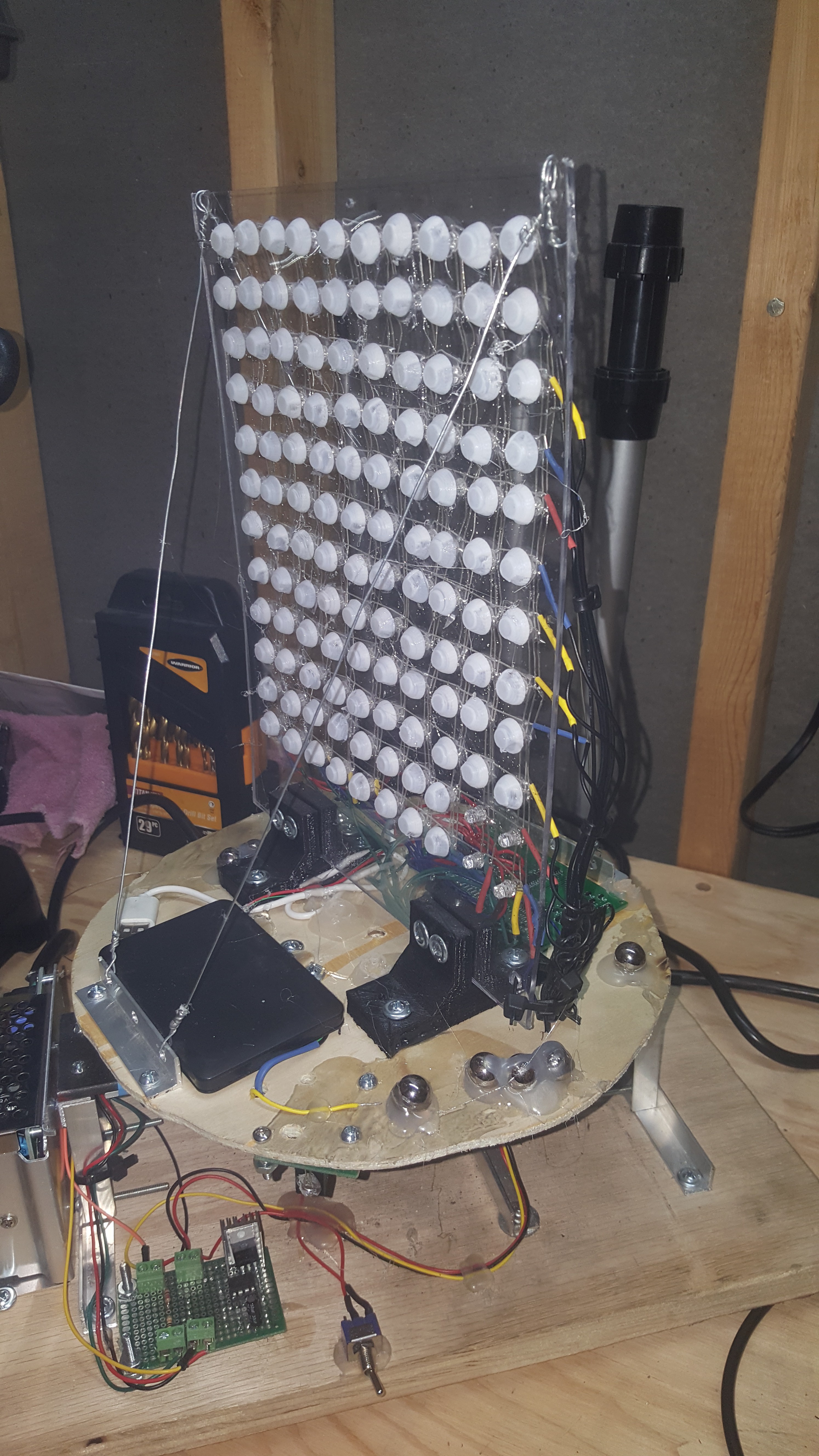
Previously there were three key issues with the mechanical elements of the display:
- The display image would shake back and forth due to poor support of the LED matrix itself
- The main plate which supported the display would warp and bend exasperating the first issue
- The entire project would move across the surface it rested on.
For the first issue the solution was simple, add some supports. However, due to the nature of the display, having too large a support would result in it being visible to the viewer. Previously I attempted to deal with this by tensioning the corners with fishing line, but that did little to resolve the issue due to the line’s elasticity. I chose to use something stronger, in this case picture wire. The wire is significantly stronger than the fishing line, however, it required more modification and is much more visible. To use the wire, I had to make two aluminum ties down points, otherwise the wire might tear through the wood disk the matrix rides on. All and all, this works alright and isn’t visible when the display is spinning too much, but it could be better.
For the second issue there really was an easy solution, the aluminum plate just had too much give to it and couldn’t support the project properly. The solution was to stop using aluminum. Previously the main riding surface was 3mm thick 2” wide aluminum bar, that has been upgraded to 5mm thick 2” wide steel bar. The difference is night and day and the entire project works much better than it did previously.
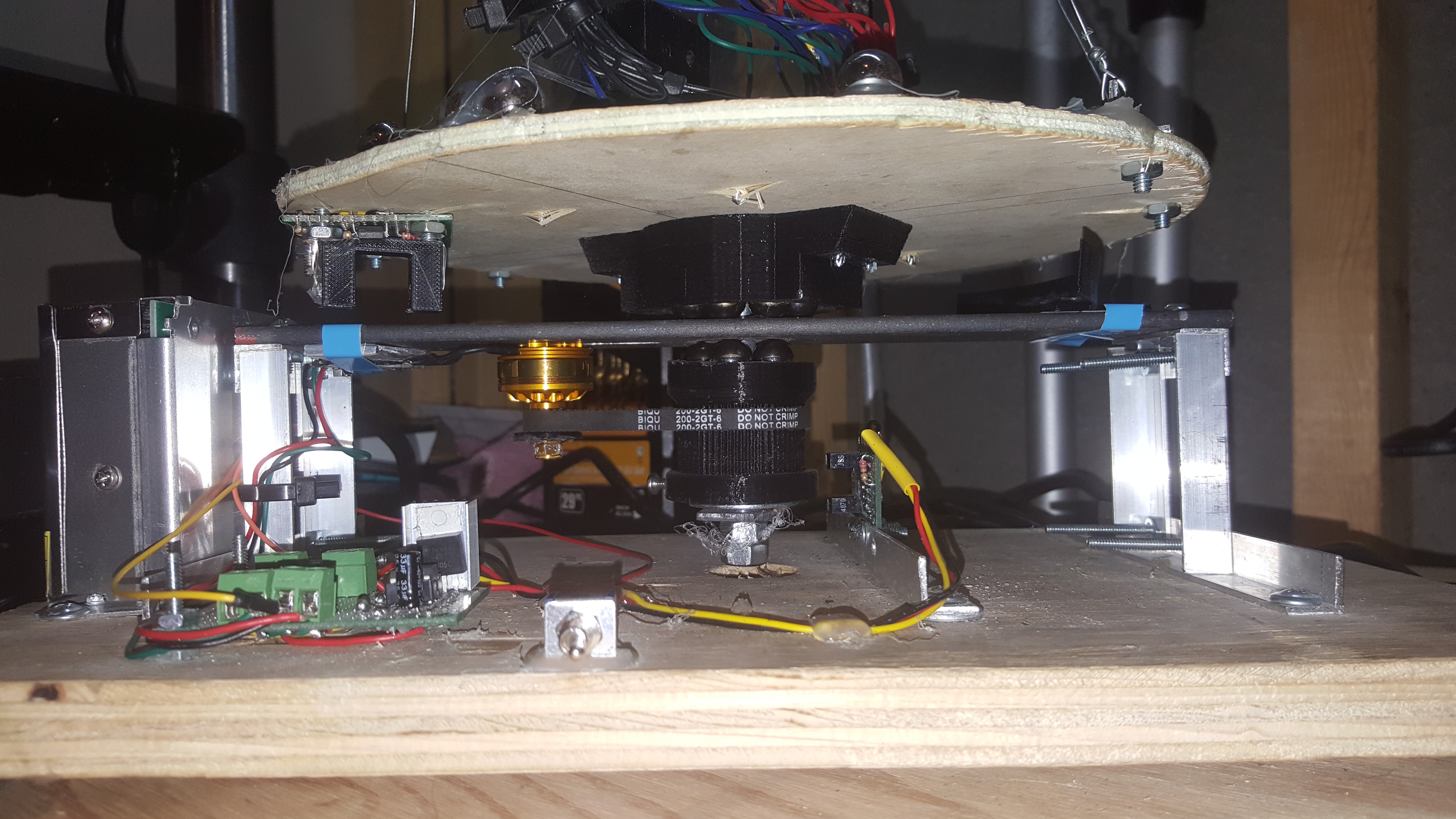
The final issue was just caused by poor balance of the rotating section, I’ve done all I can think of to balance it properly (don’t laugh at my hot-glued ball bearings!). This was corrected by two changes, firstly adding rubber feet, which should have been done from the start, but I never ordered any. The second change was to reduce the rotation speed to the minimum that would still produce a decent image. In the case of the second change the rotation speed was reduced from 16 rev/sec to 7 rev/sec and could potentially go lower at the cost of quality. I’ll cover how I know the rotation rate in the next log, hardware!
Discussions
Become a Hackaday.io Member
Create an account to leave a comment. Already have an account? Log In.