 Antonio
From https://ao2.it/135
You know what they say that constraints drive creativity, I think this post is just another little example of that.
Usually I do not put time constraints to my hobby projects, but I make sure to have some other kind of constraints, like keeping the cost low and trying to reuse stuff that I already have.
In this case I needed a way to measure the angle and speed of a rotating object for some of my projects, and I wanted a rotary encoder that was inexpensive, but precise enough to work at very low speeds.
I ruled out optical encoders (I could have reused a mouse) because there could have been noise issues in the final project, so I decided to go magnetic.
I purchased a couple of Hall effect sensors but I had no idea of how I was going to use them.
Later I realized that the US1881 sensors I bought were bipolar latching sensors (check out the Hallbook for a nice reference of magnetic sensing), meaning that their state would persist when the magnet was out of reach.
These kind of sensors are not designed to be used with the magnetic pole facing the sensor, in a reed-switch fashion, they require alternating magnetic poles to switch states; most of the time these Hall effect sensors are used with ring magnets.
I didn't want to buy a different sensor (unipolar ones may work better with sparse magnets) or a dedicated ring magnet, so I started to think about how to build a ring magnet from what I had lying around.
One way to build a ring magnet is to place small magnets with alternating poles in a circular arrangement, like proposed in Custom 3D Printed Magnetic Encoder Disks for Robotics Projects by Erich Styger.
However I don't have a 3D printer, nor such small magnets, but I had around a Tetramag: a toy made of magnetic spheres.
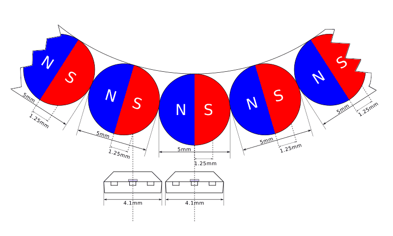
The Tetramag spheres have a diameter of 5mm, that means that a pole covers about 2.5mm (pole pitch) and that the "element pitch" (the distance between the two sensing elements) should be of about 1.25mm.
Check out the section about quadrature in the Hall-Effect IC Applications Guide from Allegro Microsystems for more info.
In practice, though, the two sensing elements do not necessarily need to be adjacent and cover the same magnet, it's enough that they are in a position which results in a quadrature signal: with the two channels being out of phase of about 90 degrees, like shown in the following picture:
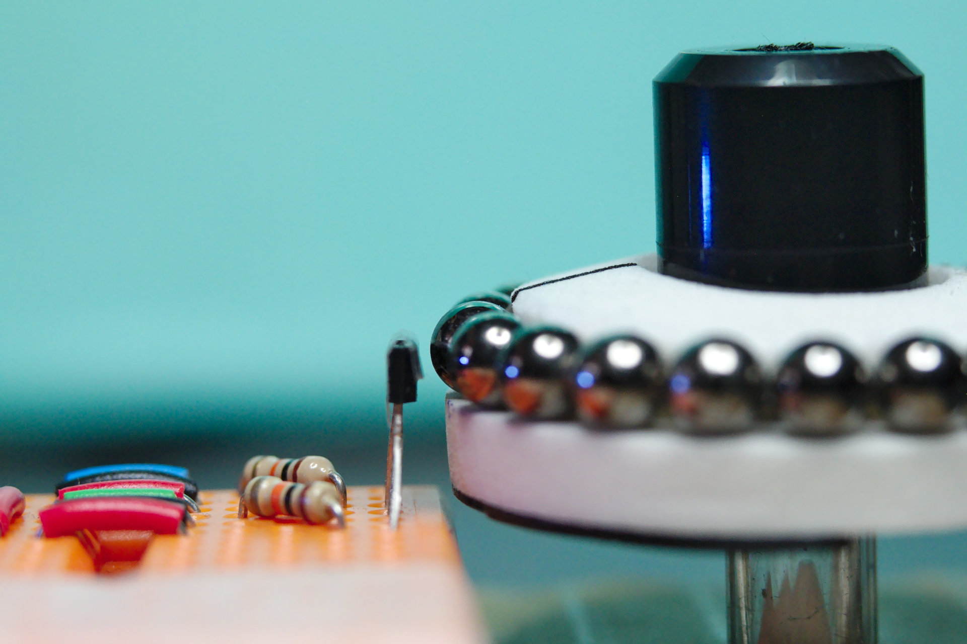
And here is a photo of the sensors position in real-life:
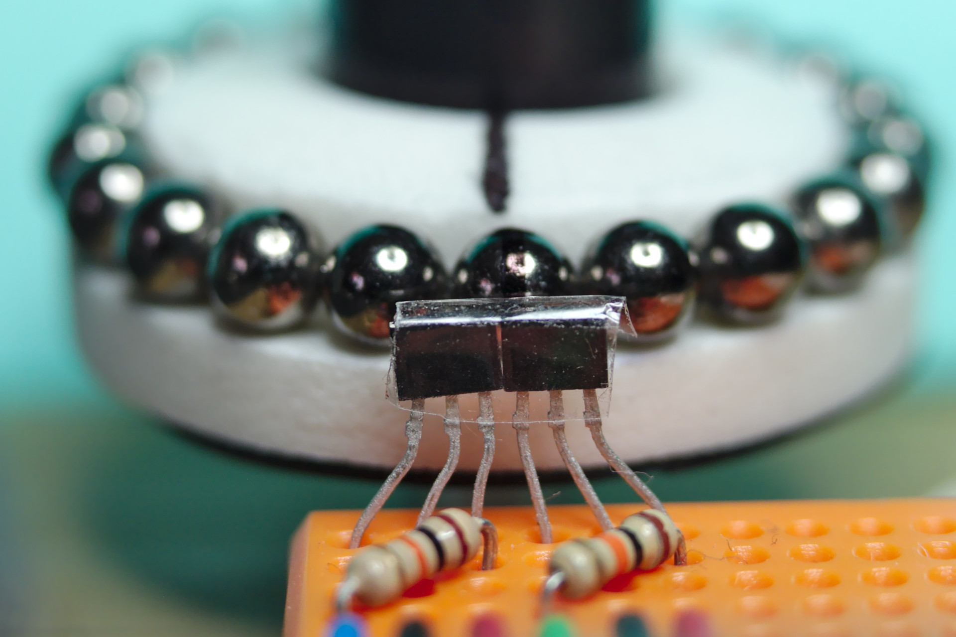
In my demo setup, a piece of a pen was used as the spindle and pieces from a CD stack case are reused for the knob of the encoder:
The result is a low-cost rotary encoder, with a precision depending on the number of spheres used to build the ring.
Look at the demo built with 21 spheres:
In this case the encoder has 21 x 4 = 84 pulses per revolution (it's a 2 channels quadrature encoder) and can measure angles down to 360 ÷ 84 = 4.29 degrees.
The code of the experiment can be found at git.ao2.it/experiments/Hall_effect_rotary_encoder.git
And now that I know more about Hall effect sensing I can decide whether a better sensor can be used for my next project: it may actually make sense to use a single dual sensor instead of two discrete sensors.
But you don't know until you know, right?
Discussions
Become a Hackaday.io Member
Create an account to leave a comment. Already have an account? Log In.