Close
0%
0%

KineMouse Wheel

Light-weight running wheel for head-fixed locomotion in mice that allows 3D reconstruction of the position of the body with a single camera.

Public Chat
Similar projects worth following
Who says you can't reinvent the wheel?! This running wheel for head-fixed mice allows 3D reconstruction of body kinematics using a single camera and DeepLabCut (or similar) software. A lightweight, transparent polycarbonate floor and a mirror mounted on the inside allow two views to be captured simultaneously. All parts are commercially available or laser cut.

This was designed by Richard Warren (https://richard-warren.github.io/) in Nate Sawtell's lab at Columbia University. Thank you to Judah Hoffman for help with the protocol, and Tanya Tabachnik for valuable design input.

Please cite our paper if you use this in your research: https://elifesciences.org/articles/63596

NOW AVAILABLE FOR PURCHASE AT LABMAKER: https://www.labmaker.org/products/kinemouse-wheel/

And remember to be nice to your mice! Put running wheels and other toys in their cage to make them stay happy and learn better. Thank you!

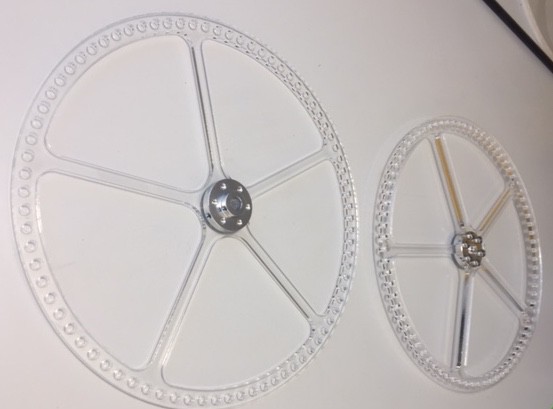
This wheel allows you to capture two orthogonal views with a single camera, facilitating 3D reconstruction of body kinematics using DeepLabCut software. This wheel is also lightweight, allowing mice to run quickly and happily. I recommend using Bonsai software for image acquisition. We also have had success with FLIR cameras for high speed tracking.

The version of the wheel described below is made primarily of acrylic and polycarbonate. However, if you have a need for speed we use a modified version of this wheel that is sturdier and more lightweight. This is accomplished by using a thin aluminum spokes panel, and by cutting slits directly into the polycarbonate for traction and weight reduction. Both of these modifications require water jet manufacturing, and therefore increase the cost to several hundreds of dollars. Please reach out if you would like to know how to build this fancier version of the wheel.

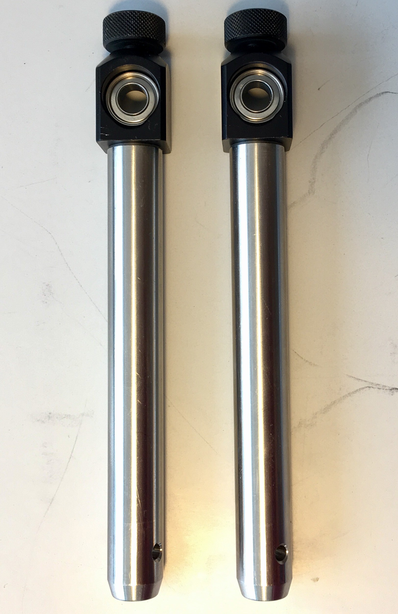
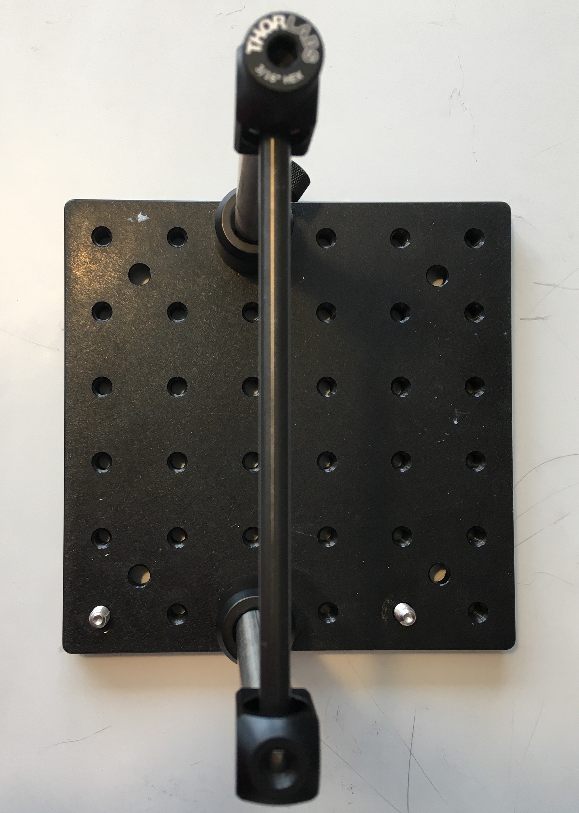
If you would like to measure movement of the wheel, I recommend using a rotary encoder mounted on an additional post mounted in parallel with the other two. If you need advice on how to do this please reach out.

Please send pictures of your completed wheel so we can post them here!

AutoCAD DXF - 306.21 kB - 09/14/2018 at 17:54

Download

AutoCAD DXF - 312.31 kB - 09/14/2018 at 17:54

Download

AutoCAD DXF - 299.96 kB - 09/14/2018 at 17:54

Download

AutoCAD DXF - 1.18 MB - 08/28/2018 at 20:04

Download

  • 1 × Thorlabs MB8 Aluminum Breadboard 8" x 8" x 1/2", 1/4"-20 Taps
  • 2 × Thorlabs PH1 Ø1/2" Post Holder, Spring-Loaded Hex-Locking Thumbscrew, L = 1"
  • 10 × McMaster-Carr 93330A541 Female Threaded Round Standoff Aluminum, 1/4" OD, 3" Long, 4-40 Thread Size
  • 10 × McMaster-Carr 90176A102 Nylon Unthreaded Spacers (for 4-40 sized screws)
  • 32 × McMaster-Carr 91772A112 Passivated 18-8 Stainless Steel Pan Head Phillips Screw 4-40 Thread, 5/8" Long (32 screws not 32 packs!)

View all 20 components

  • 1
    Laser Cut

    Begin by laser cutting two copies of the spokes file using 1/4 inch acrylic (preferably extruded acrylic as opposed to cast acrylic) and one copy of the circle file using 1/8 inch acrylic. Each piece should be 7.5 inches in diameter. If the size is wrong there may have been an issue with the scaling of the file in your printing software.

    Attach the Polou mounting hub to both spokes using 4-40 screws.

  • 2
    Mount poles

    Mount Thorlabs RA180 clamps to TR4 posts, and clamp the ball bearings inside the clamps without over tightening.

  • 3
    Mount on breadboard

    Insert the posts into two PH1 post holders separated by 5 inches on the breadboard. Cut aluminum shaft to length of 5 inches.

View all 15 instructions

Enjoy this project?

Share

Discussions

Similar Projects

Does this project spark your interest?

Become a member to follow this project and never miss any updates