 mitchell.dokken
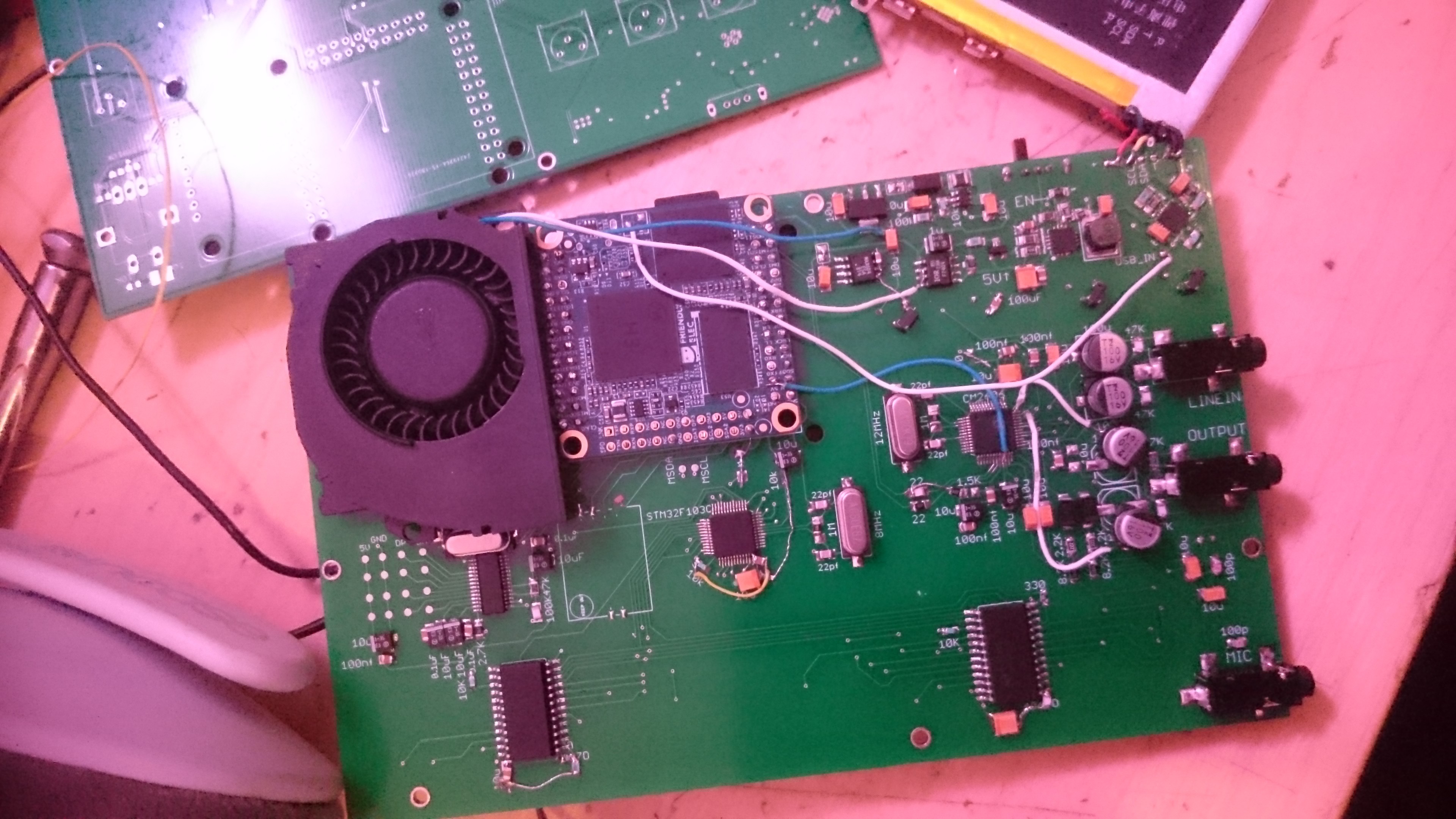
It works! After some bodge wires and double checking everything, it successfully boots into a working clone of the organelle! Its smaller and costs about $80 to make, and its all open source! It is only a first-pass at this, I do intend to make it better.
Hopefully this post will detail how the device works in a way that makes sense.
The power supply circuit is lifted pretty much wholesale from adafruit's powerboost 1000. The li-on charger and power mux IC looked really great, and the DC-DC boost converter they used seemed extremely efficient. It also has rave reviews on people's portable emulator project, so I'd seen it around. I've never soldered qfn, so I got chipquik on my digikey order. I then realized that a power supply done in chipquik is an awful idea, but I had no other options. I slowly soldered the circuit, first doing the battery management IC, and testing along with a battery and a 5v in from a USB cable. It did what it said on the box, so I moved to the DC-DC converter. This one also seemed to do what they said it would do. Shortly after this, things fell apart.
I had spec'd out a DC boost to around 6.5, for a 5v clean output for the audio card. The nanopi's 5v line gets so polluted by all the fast switching from various sources. I used the same circuit all those cheap MT3608 boost converters from china use. They work, in my experience, and you can get 40 of them, shipped to USA, for about $6. The 5v reg is an MIC2920, just because I had them in stock. Their LDO characteristics aren't bad, either. There is another 3.3v line for the STM32, mainly so it's ADCs are a little bit cleaner. I used a MAX604, since I had it around.
I should probably explain that I got extremely lucky on craigslist a few years ago and ended up with the entire stock of a local 90's telecom that went under. I've got loads of parts, mostly jellybean stuff, but all of it is labeled and inventoried. I didn't get it that way, the labeling took months. This will help to explain the footprint size of the capacitors and resistors. I wish I could just used 0603 parts for everything, but its better for me to do what I have on hand.
Right away the 3.3v line had a short. After hunting around, I found something I'd overlooked in eagle. I felt very stupid. Clearly a short from some previous trace before I'd added the ground plane.
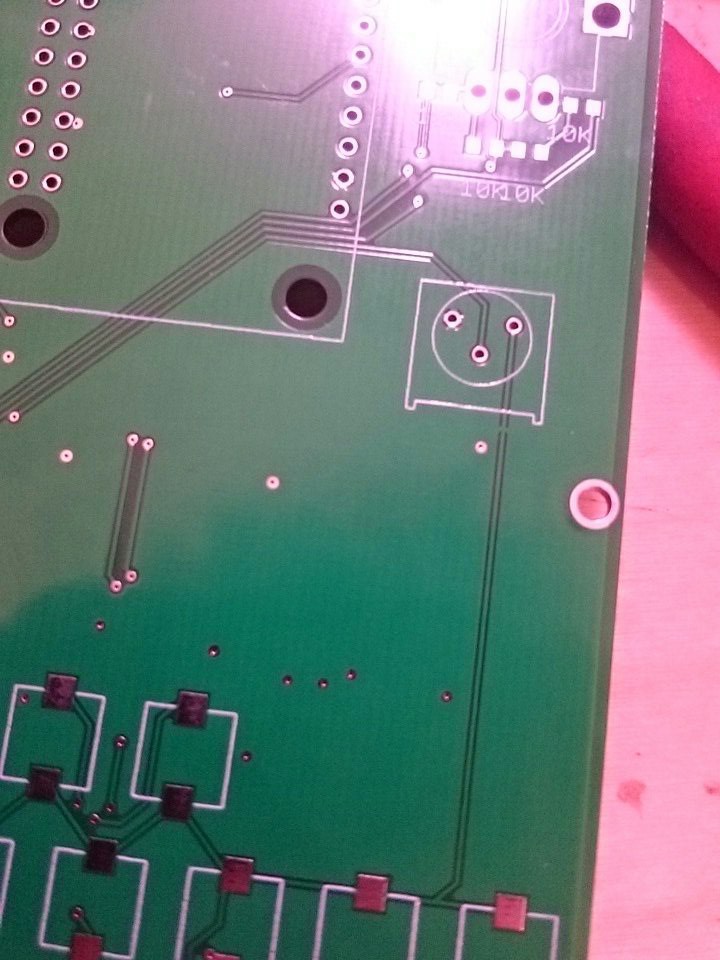
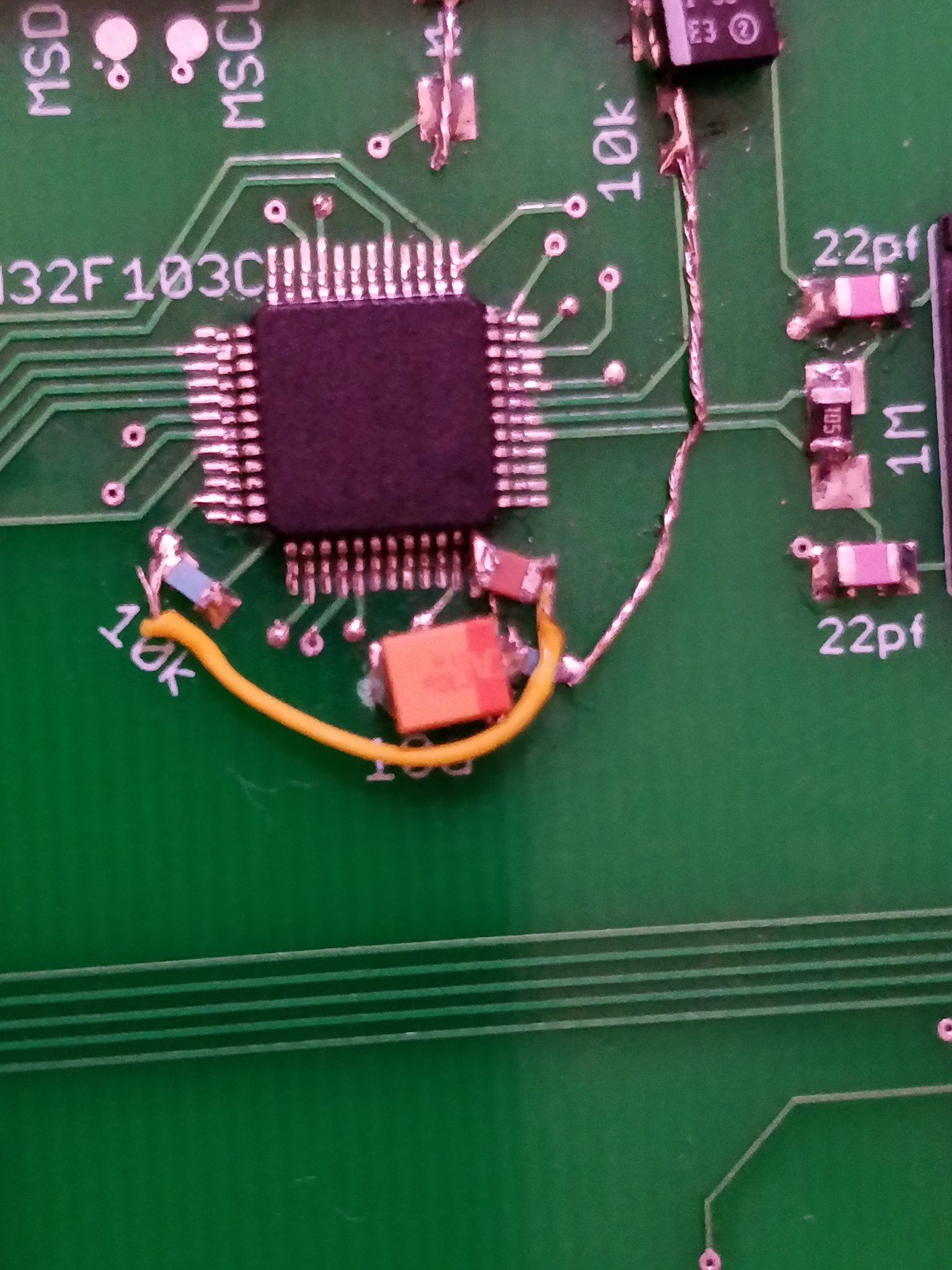
Had to use my scalpels to slice it. Swapped out the MAX604 and we were off to the races. Except the STM32 now would not flash. It turned out I'd misinterpreted the reference schematic I was looking at, and misplaced some pullups/capacitors. Bodge wires fixed that up well.
I also had to tweak the software on the nanopi, as the reset and boot0 pins have to always be initialized. I use stm32flash to do the business. Since the nanopi doesn't have a compiler, I rsync the bin from my desktop the board, then have a bash script which handles the flashing. It works reliably now!
I also misinterpreted about the same thing on the button debouncing for the rotary encoder's switch. A similar bodge occurred there.
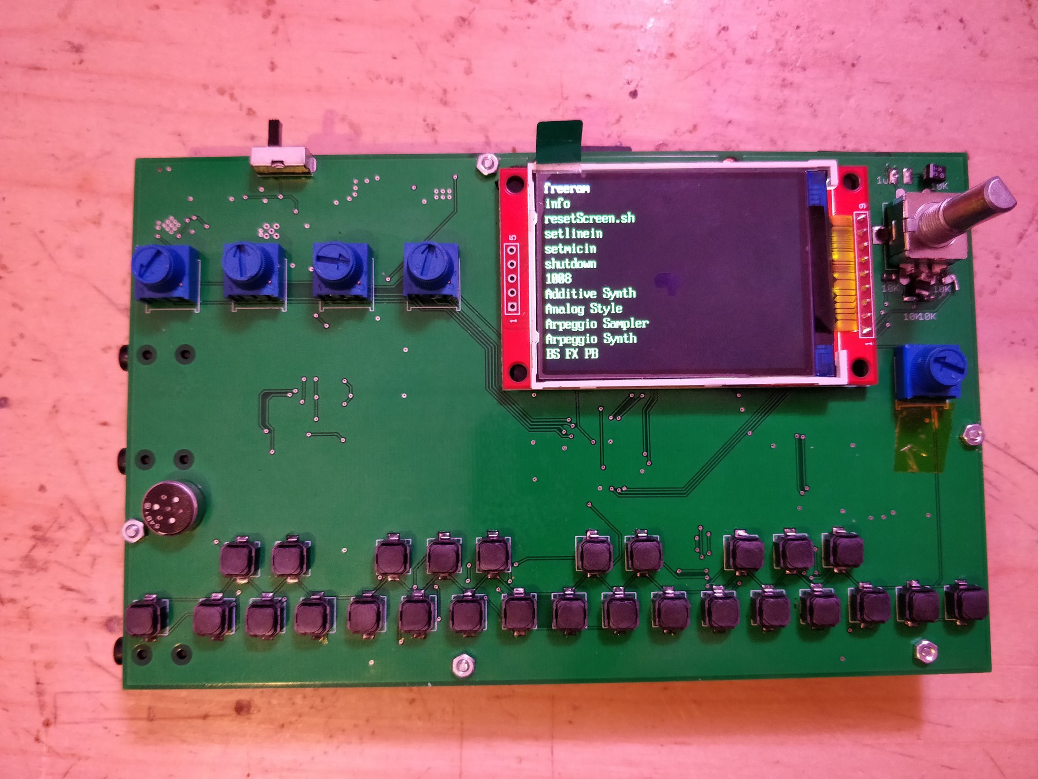
I was getting pretty scared that the 2.2 inch TFTs I ordered at the end of august wouldn't show up before the deadline, so I bought two for about double the cost, shipped locally. I still hadn't tested my footprint from the first revision, so its all pretty up in the air whether its going to work. To fit in space for a hypothetical fan that may or may not be needed, I moved the nanopi a bit, and flipped the screen layout to give me about 42mm. I knew I could flip the screen in software, I just didn't expect it to be that easy. Oh, and I messed up by one GPIO on the pinout from my prototype, so I had to tweak it in software. Then it worked like a charm!
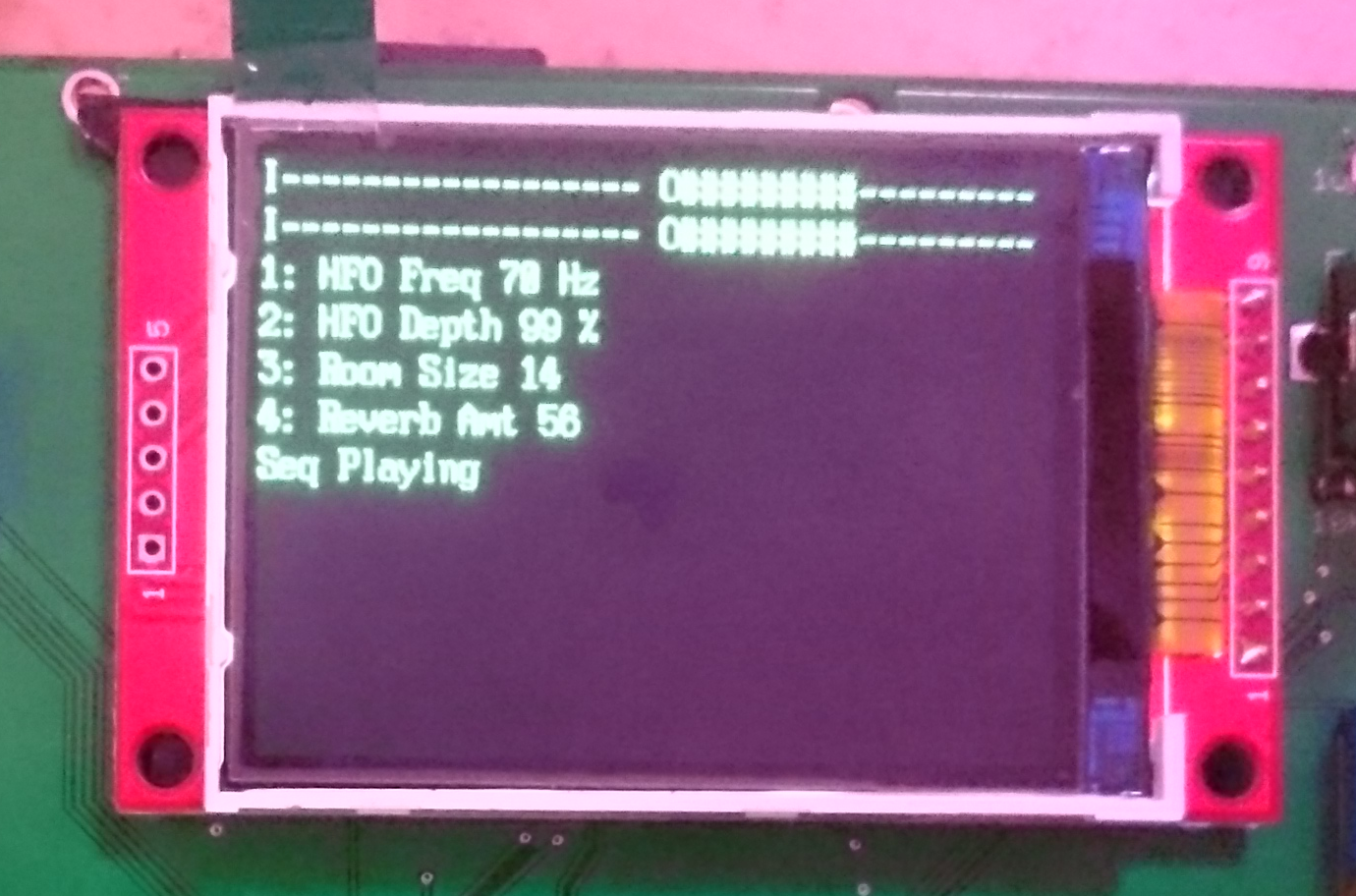
My phone's camera is a piece of shit. It looks quite clear to human eyes, even with the screen protector.
Next up, I had to get the button array working. They all soldered into place real well, but I encountered an issue I'm sure you've all seen: the 13th button was registering as the 10th. The 10th one worked like you'd expect. There aren't any shorts in the hardware. As soon as I realized the problem, I wrote a dirty solution which worked. Stupid newline/carriage return stuff! I could have swore the OSC/SLIP protocols got around that, it must be something in puredata. So that was thankfully an easy fix.
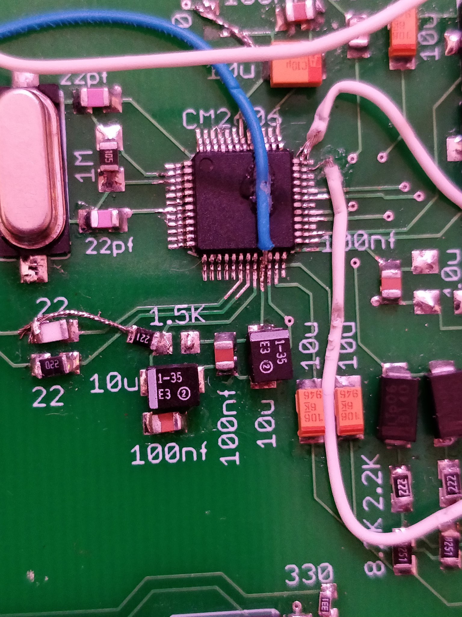
Finally, and only just today (Sunday Oct 7, the day before the contest ends) I got the USB soundcard to work. It turns out that when I ordered the chips in august, the semiconductor company was moving their warehouse from california to texas. I do not envy them. The chips finally arrived about last week. I'm not bitter or complaining, just a warning to check your sources before you hit the buy button. I was backed into a corner because I know this chip would work, but I couldn't buy it from anywhere but there. Anyway, the C-Media 6206 is used in those really cheap USB soundcards with a bunch of outputs. In my prototype it worked really well (after power filtering via DC-DC boost -> LDO)! The reference schematic I had for it is extremely blurry, poorly labeled, and really overall just bad. There was JUST enough information left after compression to get it to work.
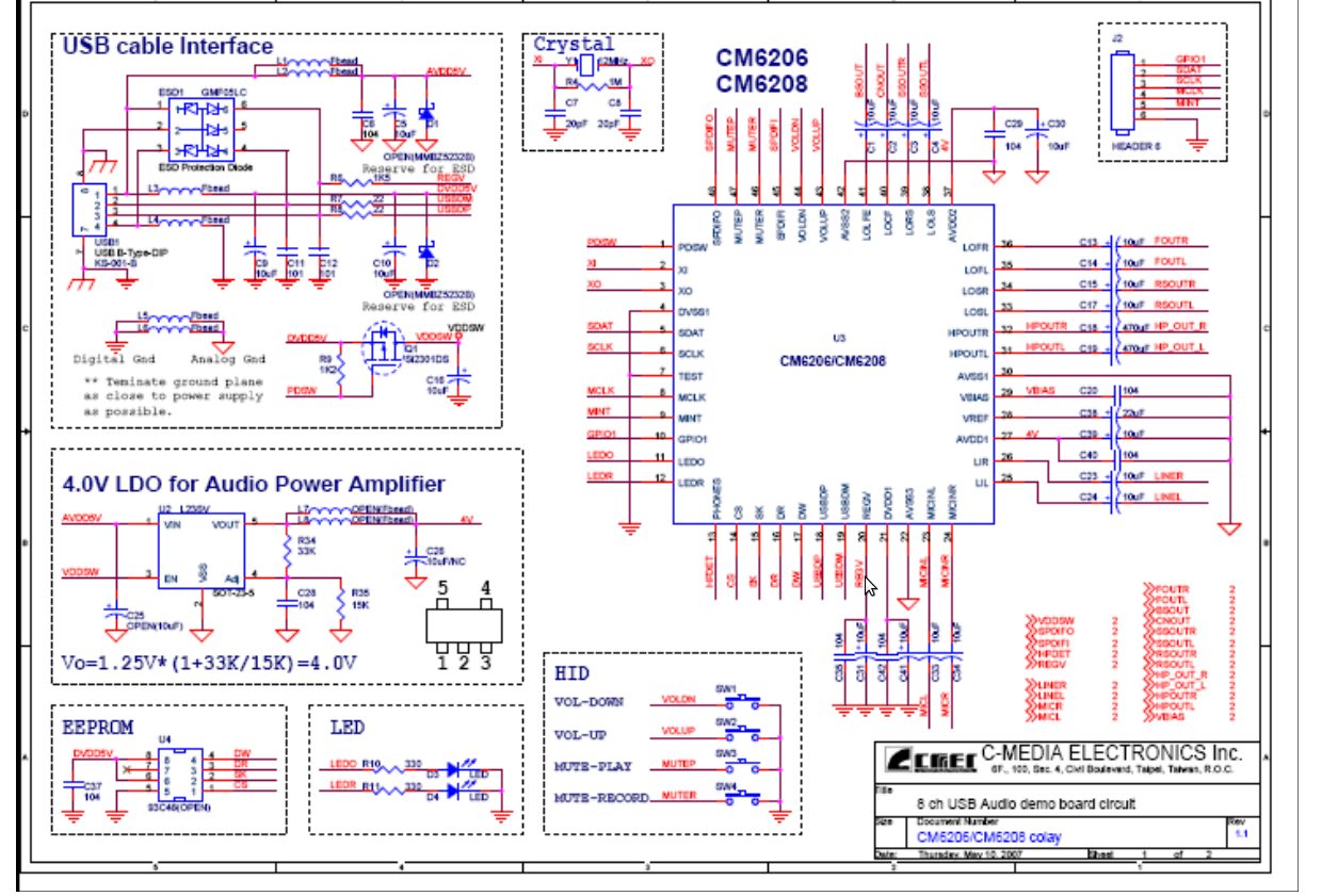
I realized I goofed when I tied the REGV line to 5v through 1.5K ohms instead of the USB Data Plus line. It seemed like a bizarre typo, but I verified it with the soundcard I'd purchased earlier. After that, it still didn't work like I'd expect. I imagine it has to do with the 4.0v LDO for the power amp. I instead bodged again, and pulled the LOFR and LOFL lines right into the output caps. It worked!
Thats the hardware part of all of this. A single toggle switch pulls the enable pin on the initial DC-DC boost converter. That takes the power from either the battery XOR the microUSB input. Then it goes straight into the nanopi, which does its own 3.3 volt regulation. A separate 5v and 3.3v are sent to the USB soundcard and STM respectively. The TFT is powered by the nanopi's 3v3 line. Those all operate as you'd expect.
The STM sends OSC messages to the nanopi over UART 1 at 115200 baud, which gets interpreted by a python script, and sent to either puredata, the screen (using the curses lib), or some system command. The OSC messages honestly fly all over the place. The STM32 sends and receives messages, python handles All of the messages, so it has to have a handler for everything, and puredata sends/recieves over OSC. Any system script ALSO sends/receives OSC using oscdump/oscsend. Its basically a madhouse of udp messaging. Python does seem to keep up well, using 3-6% of cpu at any given time. The STM reception and PD reception processes are threaded in python.
The entire linux system is something I've been working on for about a year now, I think. I started figuring out the buildroot system, how uboot/dts/drivers/kernel/userspace work, how board bring up on a new board works, and merging patches for the Allwinner H3, all in May of last year. I basically spent a few months in my room either playing Factorio or hitting make, then playing Factorio. I managed to create a config for mainline linux which included USB OTG support, ethernet, SPI, and other hardware optimizations, running a realtime kernel. I thought that was pretty cool, and I just sorta waited for some H3 design which included breakouts for the line-in inputs or the FM-in. Any would do. Instead they just kept releasing a single mic-in as the solution. It was pretty frustrating. So I went and made a PCM2906 dev board for fun, but I couldn't solve an issue or two. I put everything on the backburner.
I spent some time figuring out the organelle worked by studying their github repos. I figured they'd be easier to work with if they were written in python, or at least more accessible languages. Their code is also out of date from what they have on the market, what with drawing graphics and whatnot, so I wanted to give it a go of workin on an open source project. I ended up with a python script over a thousand lines long, using the curses module, and rewrote the puredata mother patch to work with what I'd written for the STM and python. The whole goal was to be able to load arbitrary organelle patches and have it work. It did!
Then the hackaday contest comes up and says "heres some possible money to do something", and I said yeah why the hell not. I could probably throw all this stuff together by Oct7. I got pretty lucky with my guesswork, and I have a lot to learn regarding integrating a bunch of different stuff on a PCB. Right now Its all very much a first pass, on all accounts. The PCB design was based around the kindle battery I used. The code is functional, but not without some glitches. The screen will sometimes switch all letters to about 200 up the unicode scale. The ADCS on the STM32 are noisy and give a wide range of readings. I'm using quickchip on the power supply!
I think the most important thing would be that its possible to, very cheaply, improve on stuff out there in the wild. I see the organelle only as a starting point. Its a bit of a spectrum of Teenage Engineering's pocket operators, to Critter and Guitarri's organelle, to the OP-1 (and now OP-Z). With the current setup I have the groundwork for organelle to OP-1. I am going to create a pocket operator clone using allwinner's V3s. 64MB of ram should be enough to handle all that. The OP-1 could possibly be done on a platform like this. I left the topside of the PCB bare for this reason. I could design another board with an array of buttons matching the OP-1 and hook it into another uart. Or I could take inspiration from the square inch contest and create a bunch of synth module things in a square inch, and create a backbone of busses to run everything from. Synths get really weird when you involve a networking stack, or microcontrollers running at 72MHz.
In the future, I'd love to have something like paul stroffgen's teensy audio gui. But instead of spitting out some boilerplate C code, I'd have it spit out a buildroot config, full C code for the STM32 (based on the options you selected in the gui), a BOM, and the schematic. I suppose the PCB would be up to the end user, but it would simplify the whole "how do I make this thing that I want" when you really don't know where to begin. Hiding the work behind a node-red interface seems like a really interesting take on embedded linux systems that I haven't seen before.
Anyway, I understand that I'm supposed to upload a video of it playing. I'm really awful at playing instruments, so I'll throw something up later tonight. Thanks for reading!
Discussions
Become a Hackaday.io Member
Create an account to leave a comment. Already have an account? Log In.
How to make serial uart MIDI on nano Pi?
Are you sure? yes | no
" I understand that I'm supposed to upload a video of it playing. I'm really awful at playing instruments..."
Such a small fly, in the ointment of genius. I'm glad you got this all together in time and wish you the best of luck.
Are you sure? yes | no