 Gee Bartlett
My Idea is to try to make a individual pieces that blink but also interact with each other.
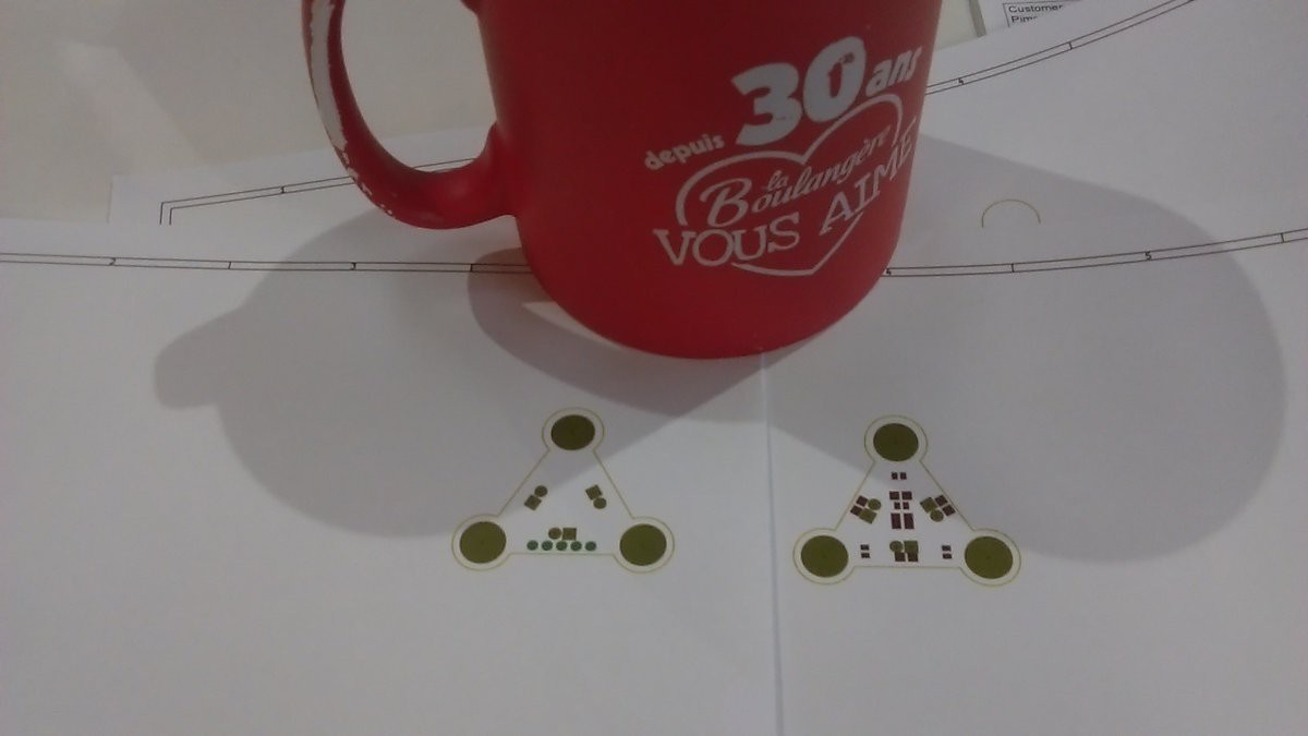
Each piece will contain:
-Battery holder ( later dropped because in impeded the boards design and function)
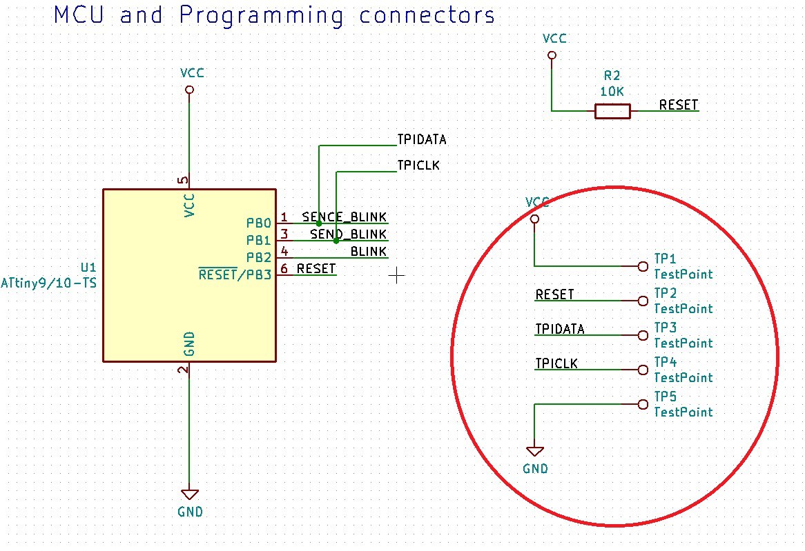
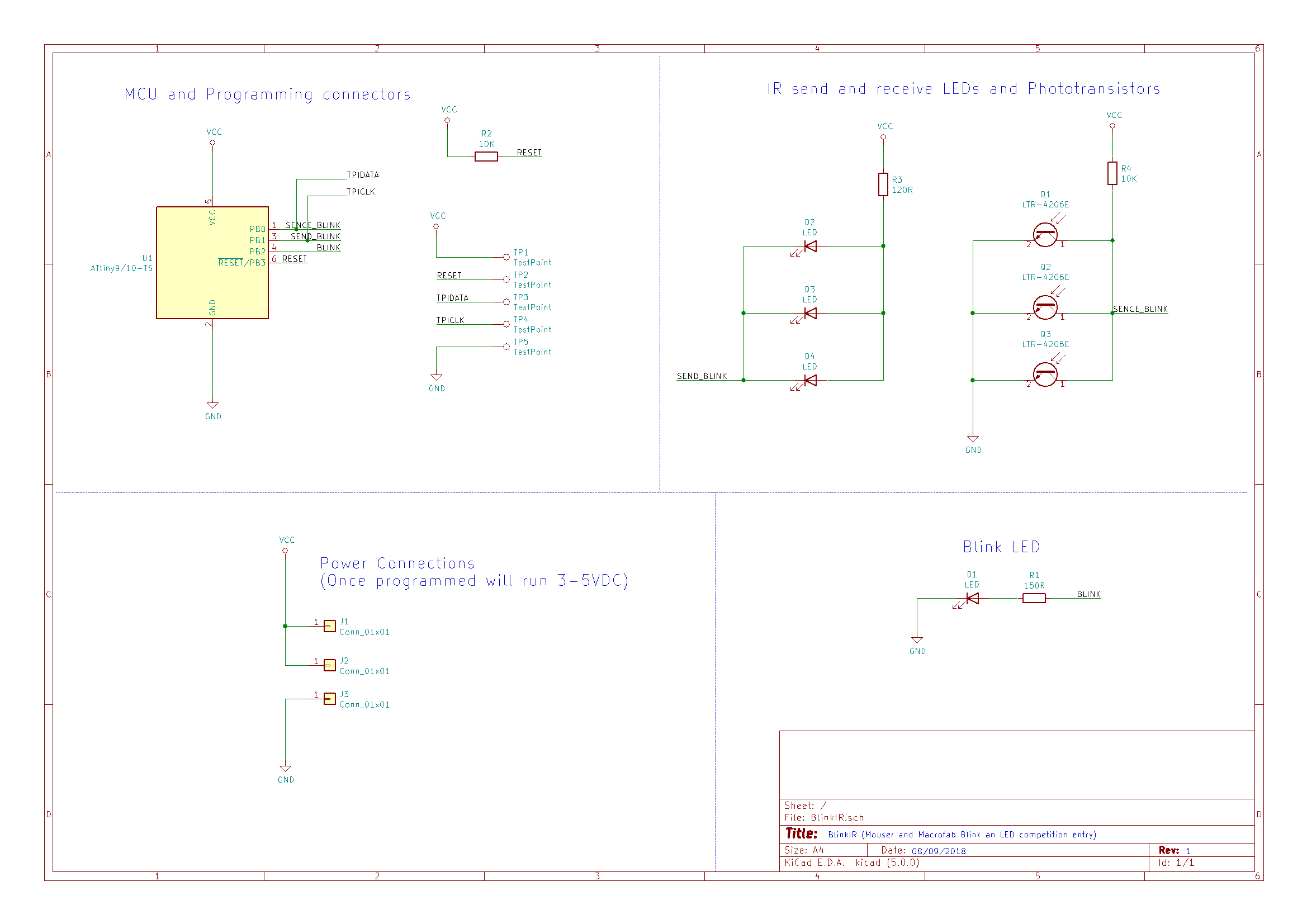
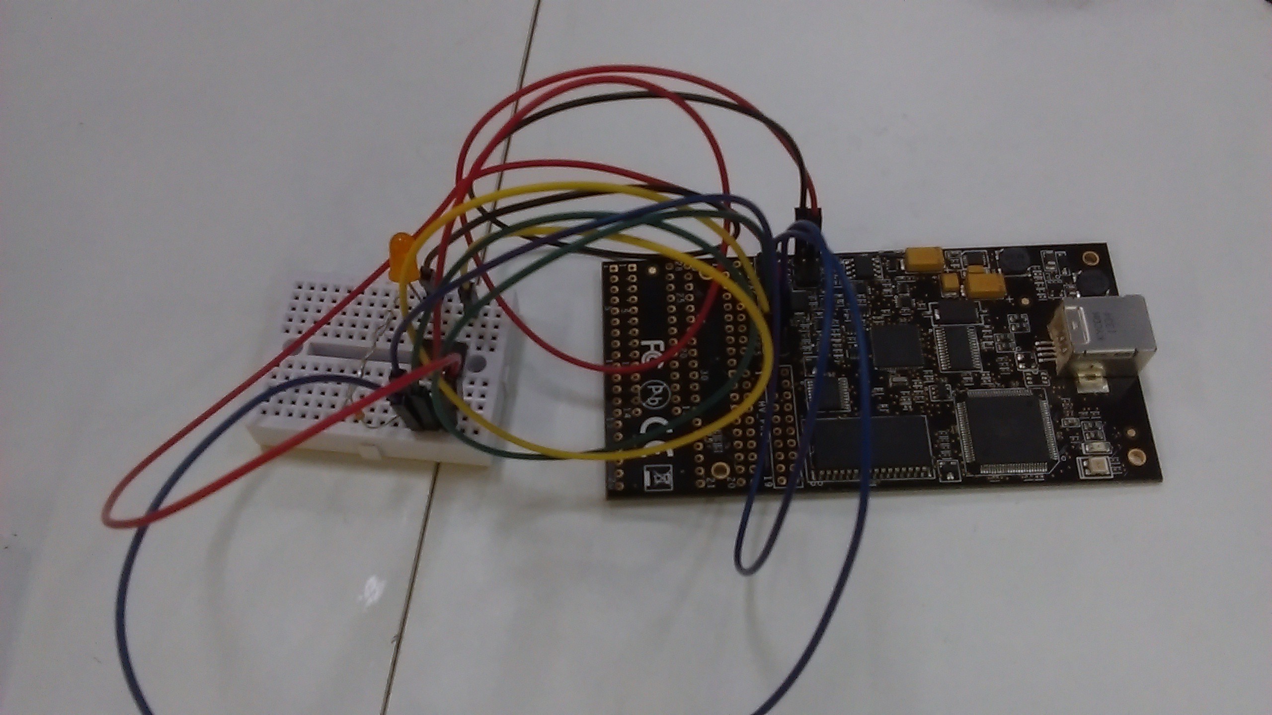
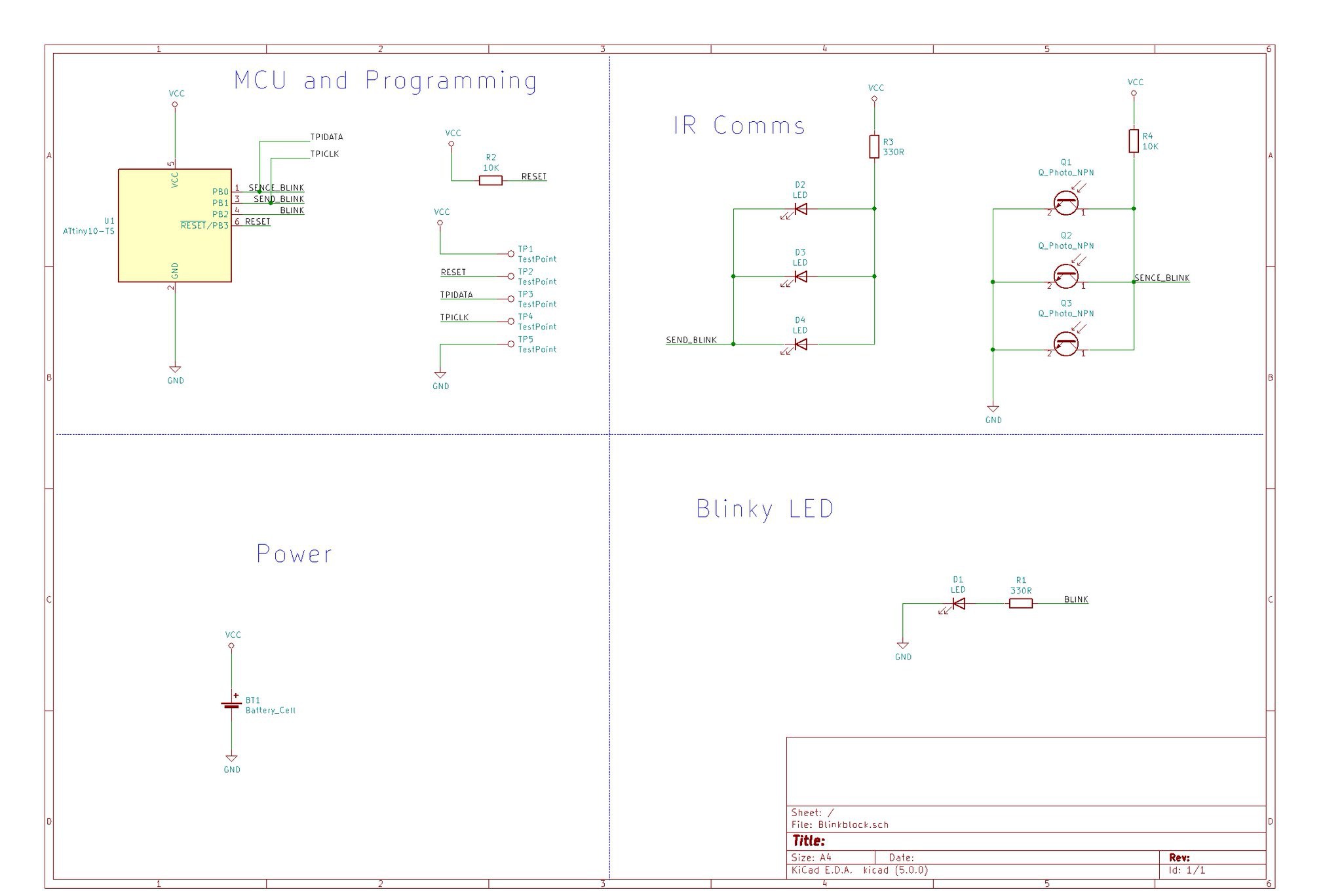
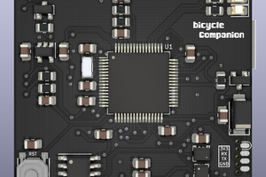
-MCU (possibly a ATTiny10)
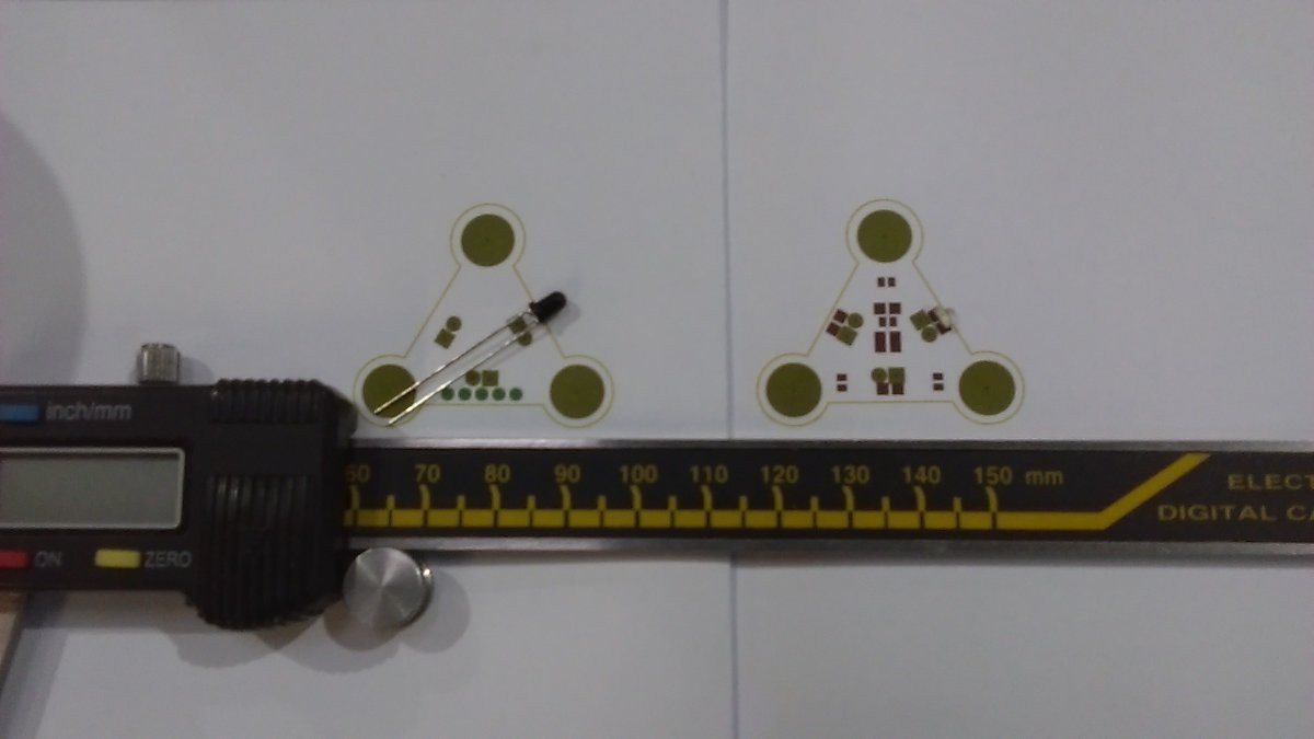
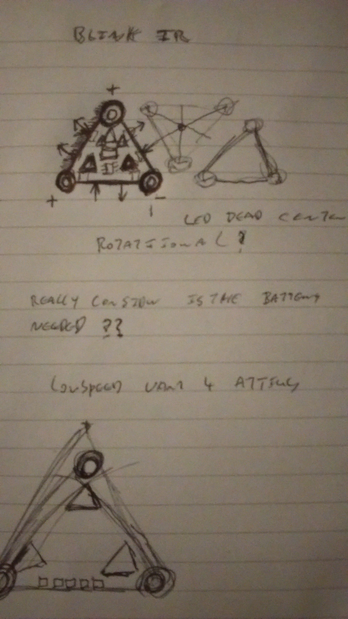
-IR Photo-transistor
-IR Diode
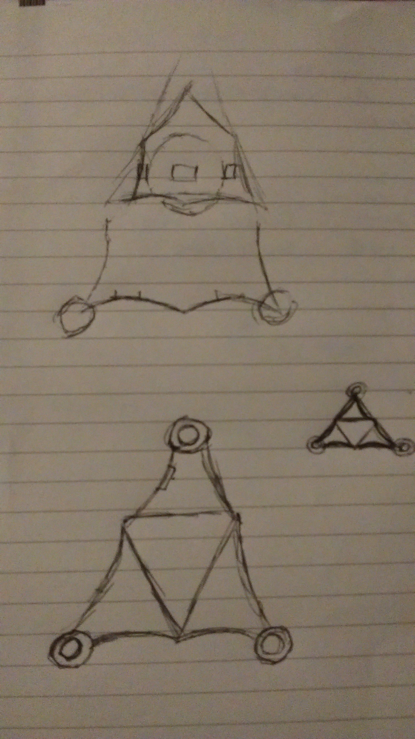
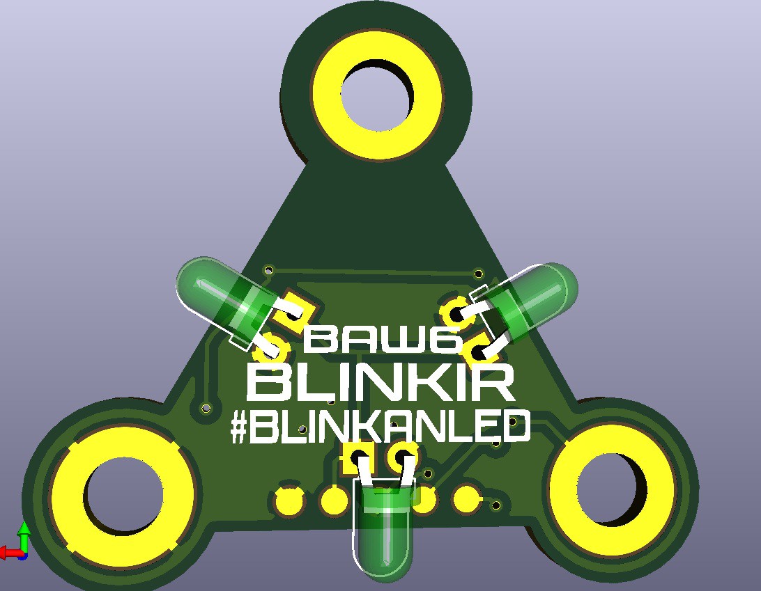
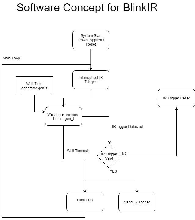
Each piece will not only blink interdependently but also be triggered by a signal sent via the an IR connection to generate organic patterns. The design is to be able to be sewn onto fabrics and clothing to great a tapestry if blinking lights.
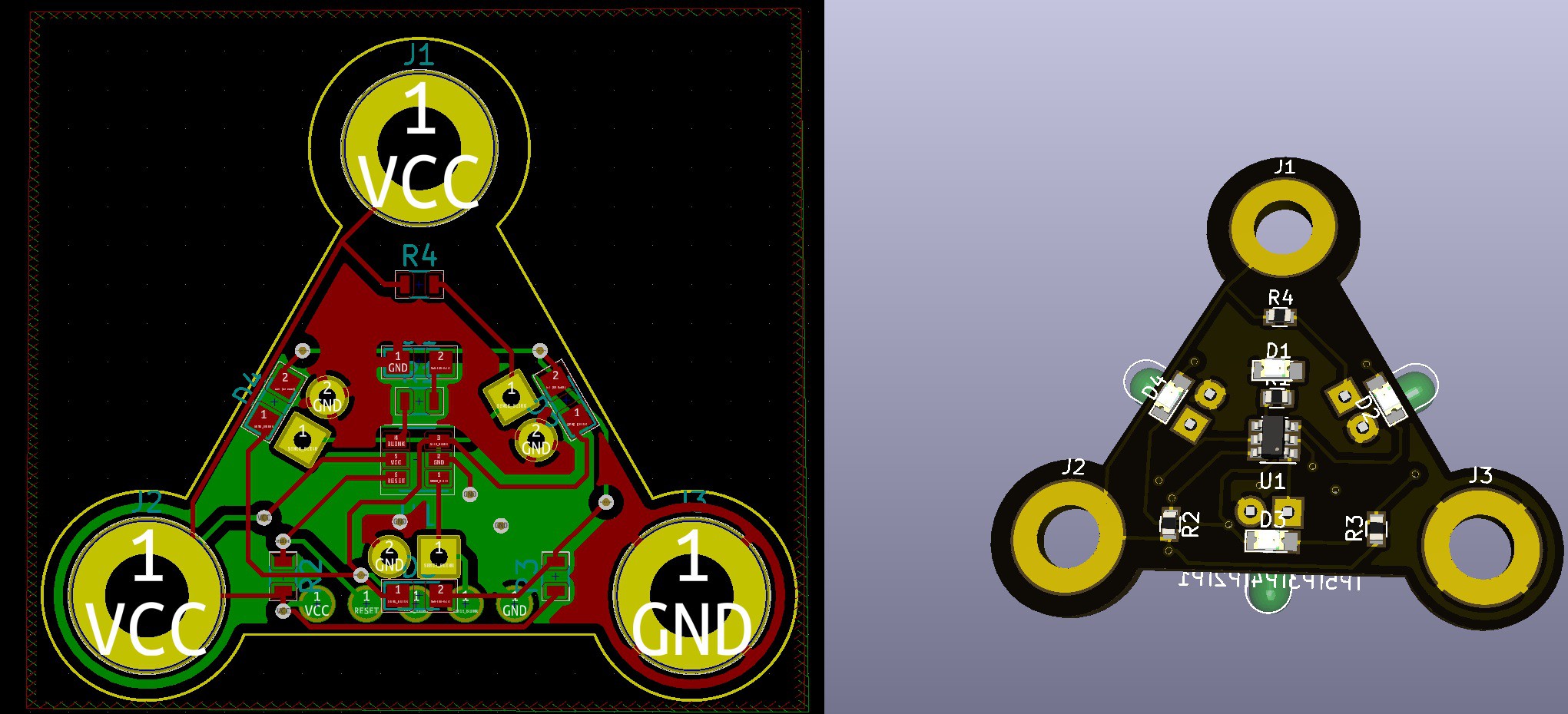
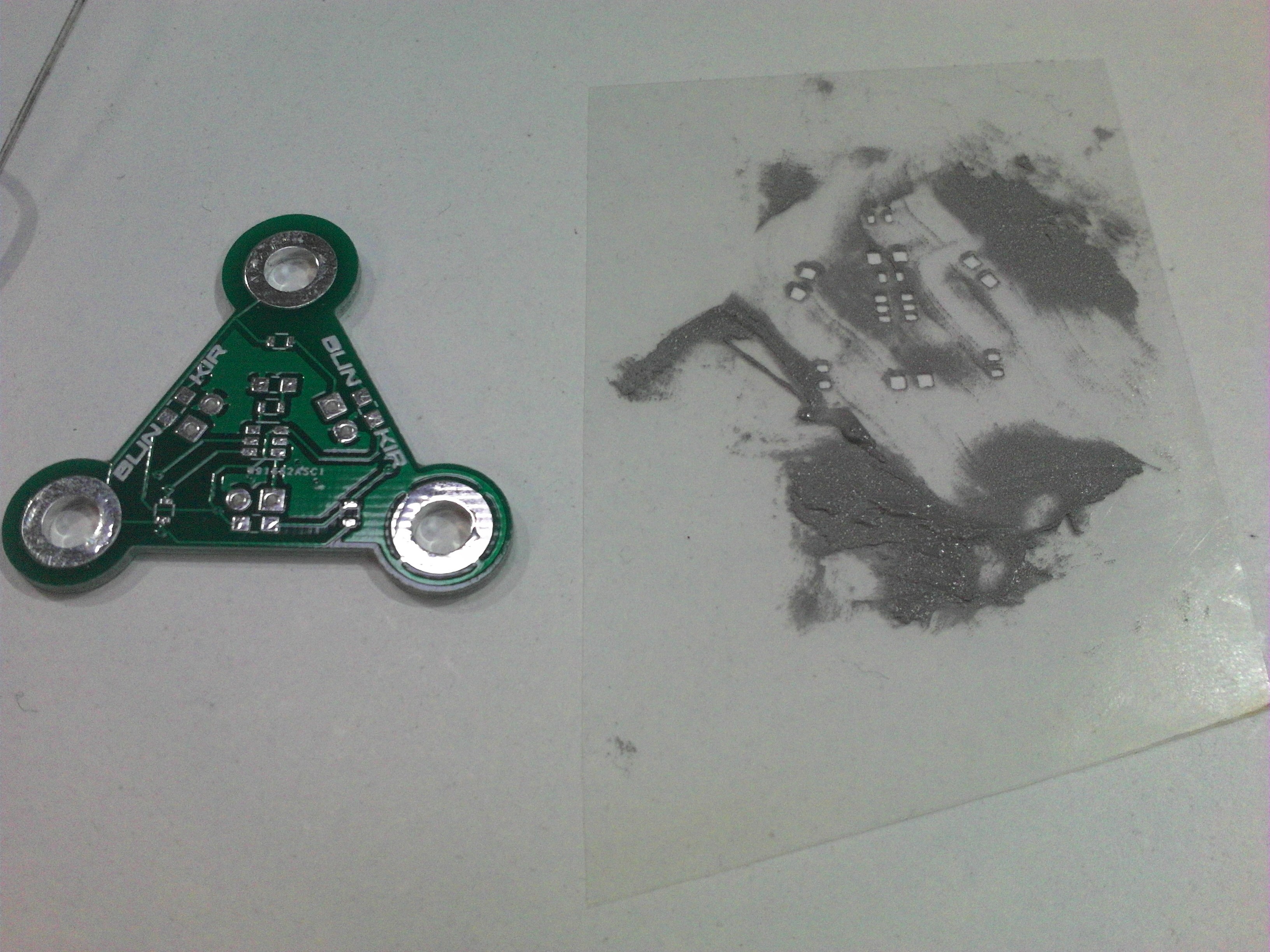
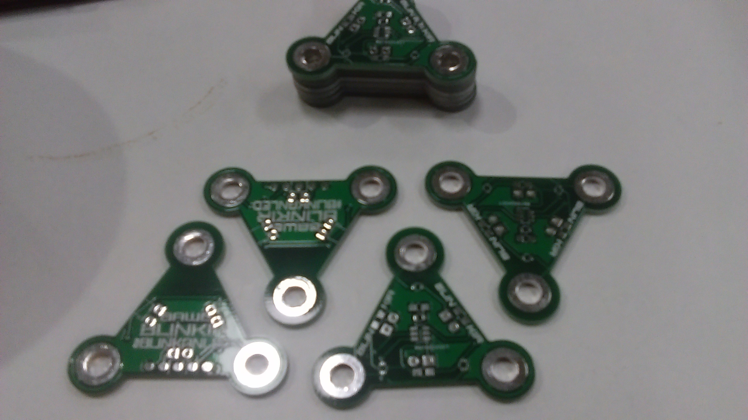
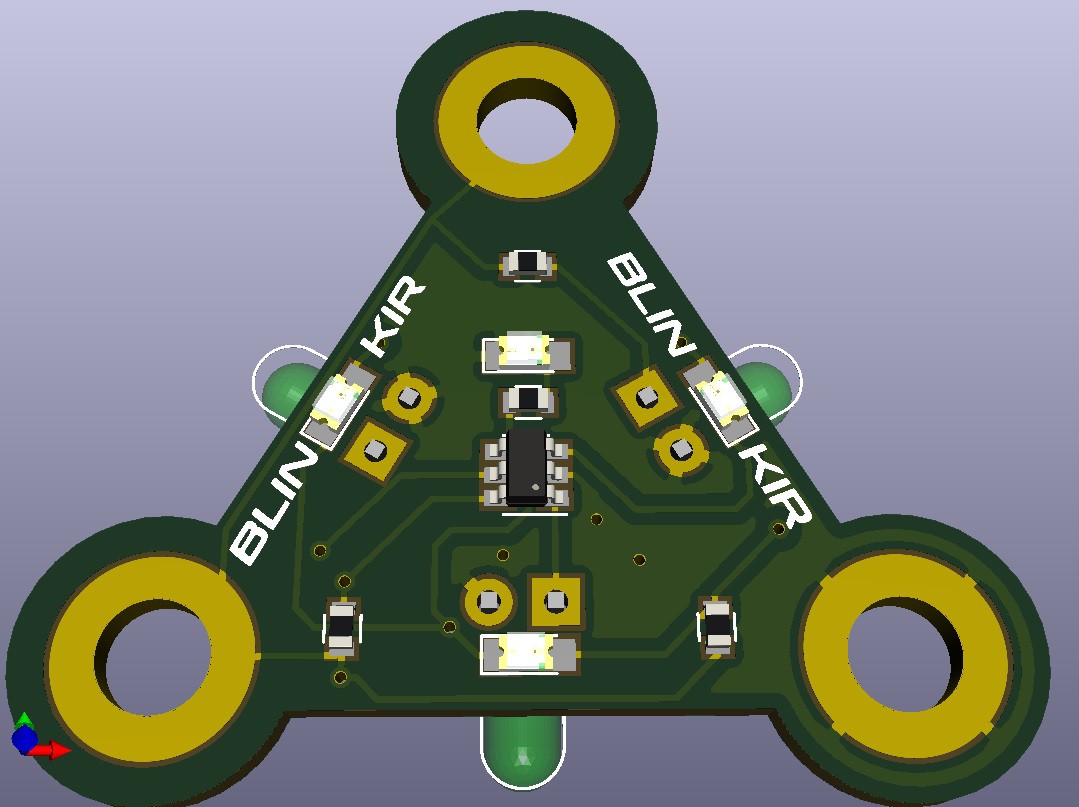
The units are triangular so they can be faced up against one another, with sew-able connection tabs in each corner so Power and Ground can be provided to each unit.
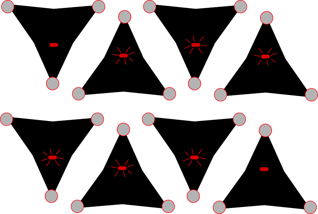
Each unit is capable of a random delayed blink sequence but when the units are placed together one unit will trigger the other 3 units adjacent to it. and they in turn will trigger other units going outwards.
The theory is that together they will make a ripple pattern of blinking LEDs similar to ripples on a pond.
All the project files can be found at https://github.com/rabid-inventor/Blink-An-LED-Entry-BlinkIR , as well as the current version upload here.

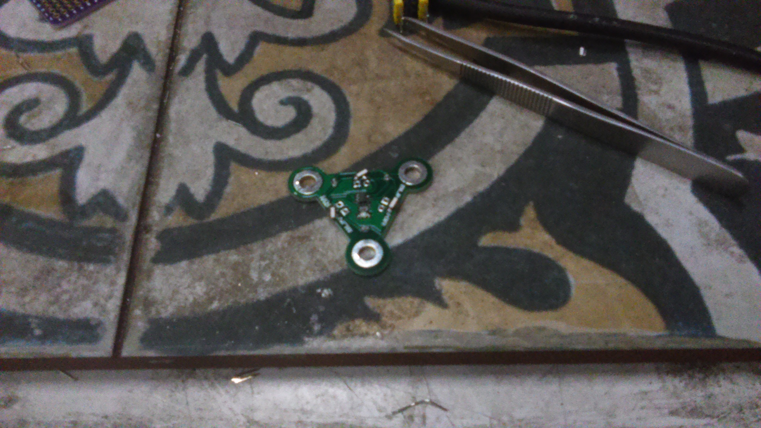 I used a solder paste dispenser and the placed the components by hand.
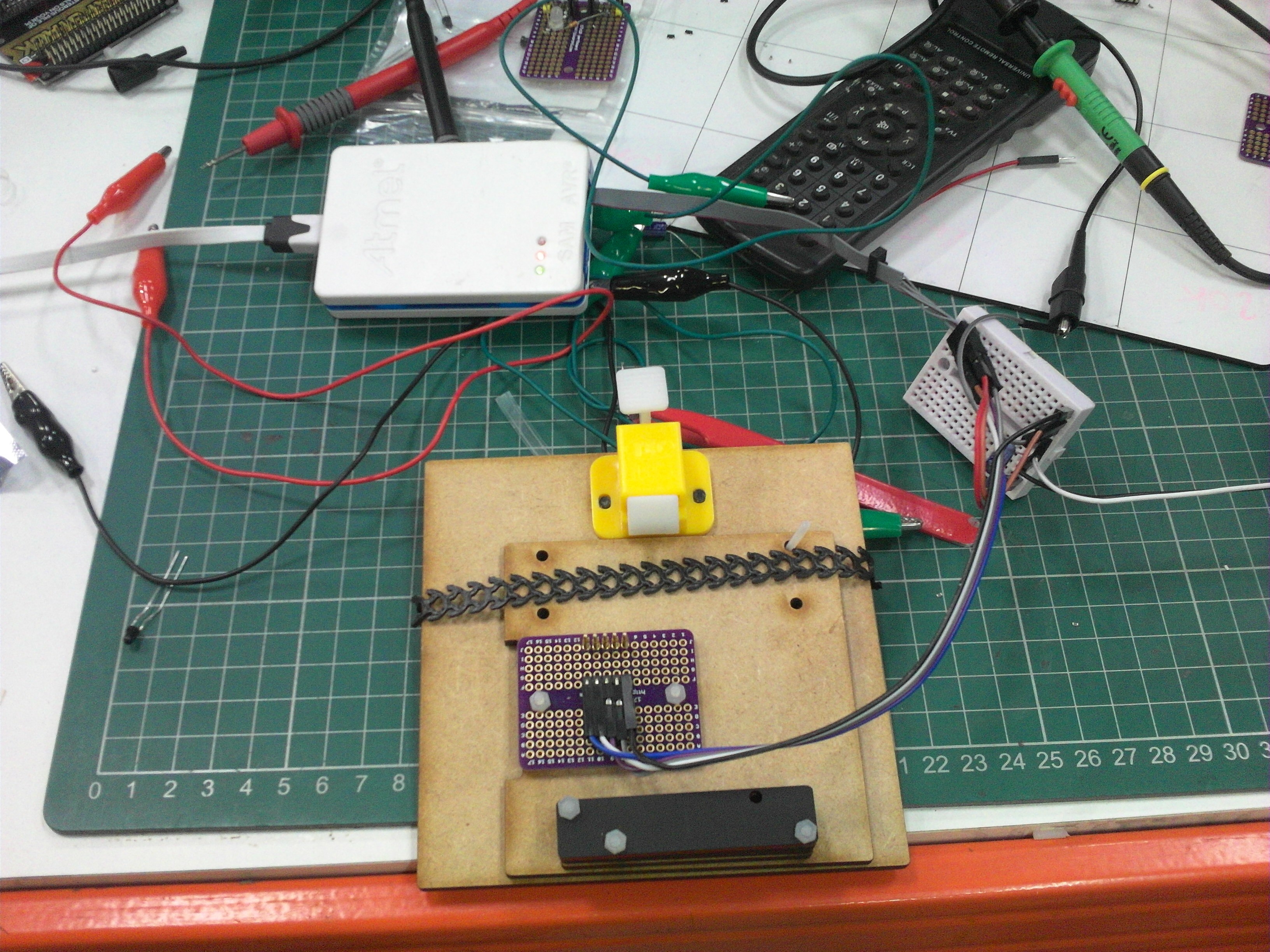


 Matias N.
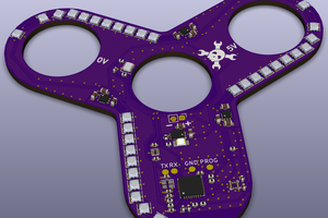
 Matthias
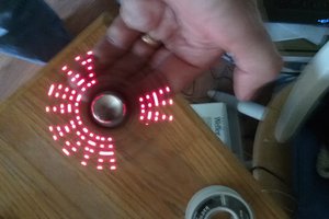
 Jon Thomasson
 Mike Kushnerik