 Liam Lacey
Over the past couple of weeks I've mainly been busy completing the electronic circuit for the device. All electronics have been done using wire and stripboard (rather than building a PCB), simply because this is what I feel most comfortable with.
Circuit Design
Other than needing a lot of wires to attach the controls to the Teensy microcontroller, the circuit is very simple and only requires 1 resistor (mainly thanks to the presence of the internal pullup resistors on the Teensy pins), and requires no other extra components. The main reason I chose to use a Teensy 3.6 over the smaller Teensy boards was so that all controls could be connected directly to the microcontroller without have to use multiplexers or shift registers. However as the Teensy 3.6 is probably overkill for this project in every other way, a Teensy 3.2 with some shift registers would be a more affordable option for building this device.
I will post a circuit diagram at a later date.
Teensy Pin Allocation
This device uses 53 pins of the microcontroller, leaving 6 spare digital pins and 3 spare analogue pins. I have specifically left pins 0 and 1 (RX1 and TX1) spare incase I want to add serial MIDI-DIN connections in the future.
The specific pin allocation I have chosen is based on the orientation of the Teensy in the enclosure and the position of the controls on the panel.
Click here to see the pin allocation.
Issues
Other than it taking a long time to solder all wires to all controls, the main issue I had was when soldering wires to the surface mount pins on the Teensy. On my first attempt I ended up accidentally pulling off a couple of the solder pads when trying to bend the wires into position, causing the Teensy to start behaving temperamentally (resulting in me needing to replace the Teensy board altogether). However after switch from solid core wire to stranded wire (which has more flexibility) I didn't have this problem again. I had considered using right-angle headers to access the surface mount pins, however this appears to be more suited for when using protoboard (rather than stripboard), which I personally don't like to use.
Photos
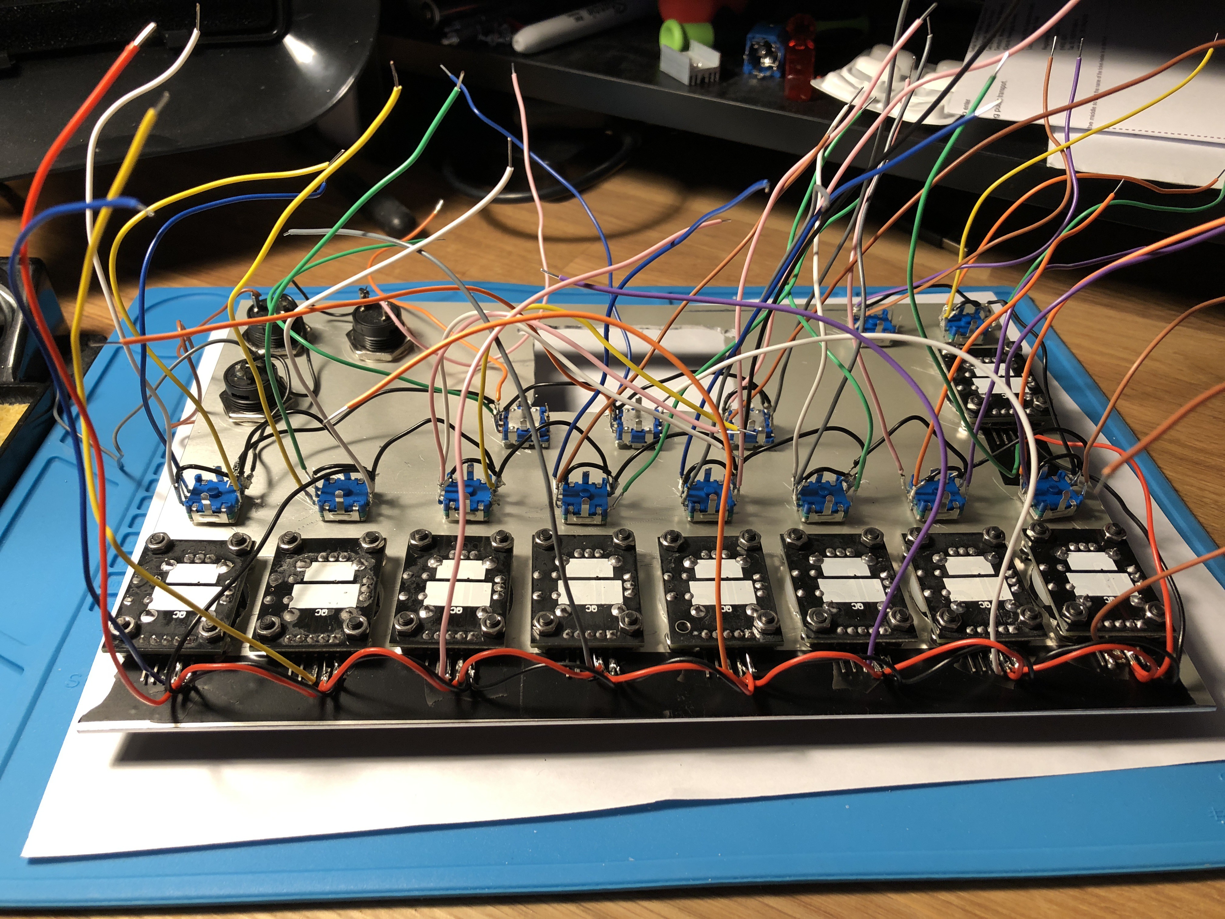
The panel control wires. GND and 3.3V wires are daisy-chained between controls.
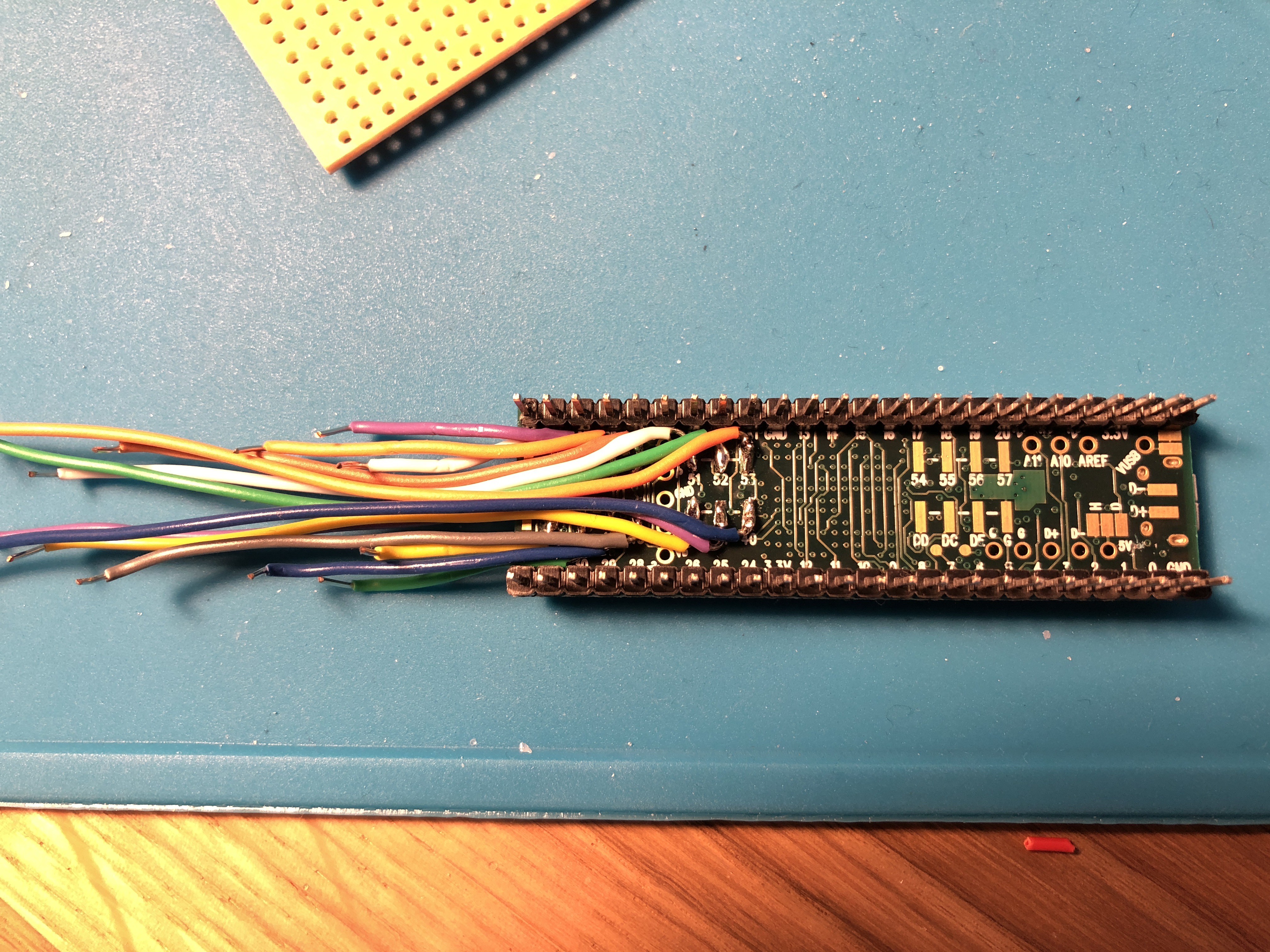
Wires soldered to the surface mount pins of the Teensy.
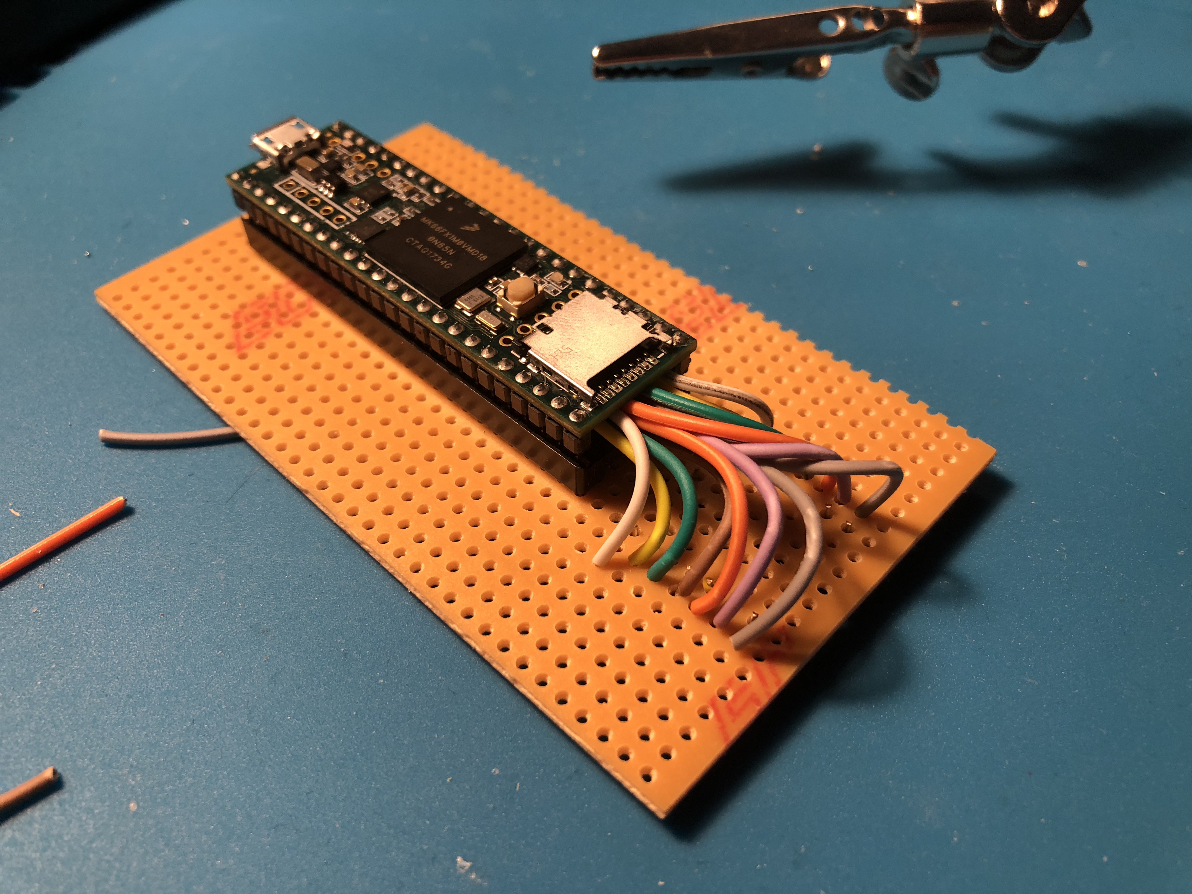
Teensy in a socket attached to stripboard, where the wires from the surface mount pins are attached to their own strips.
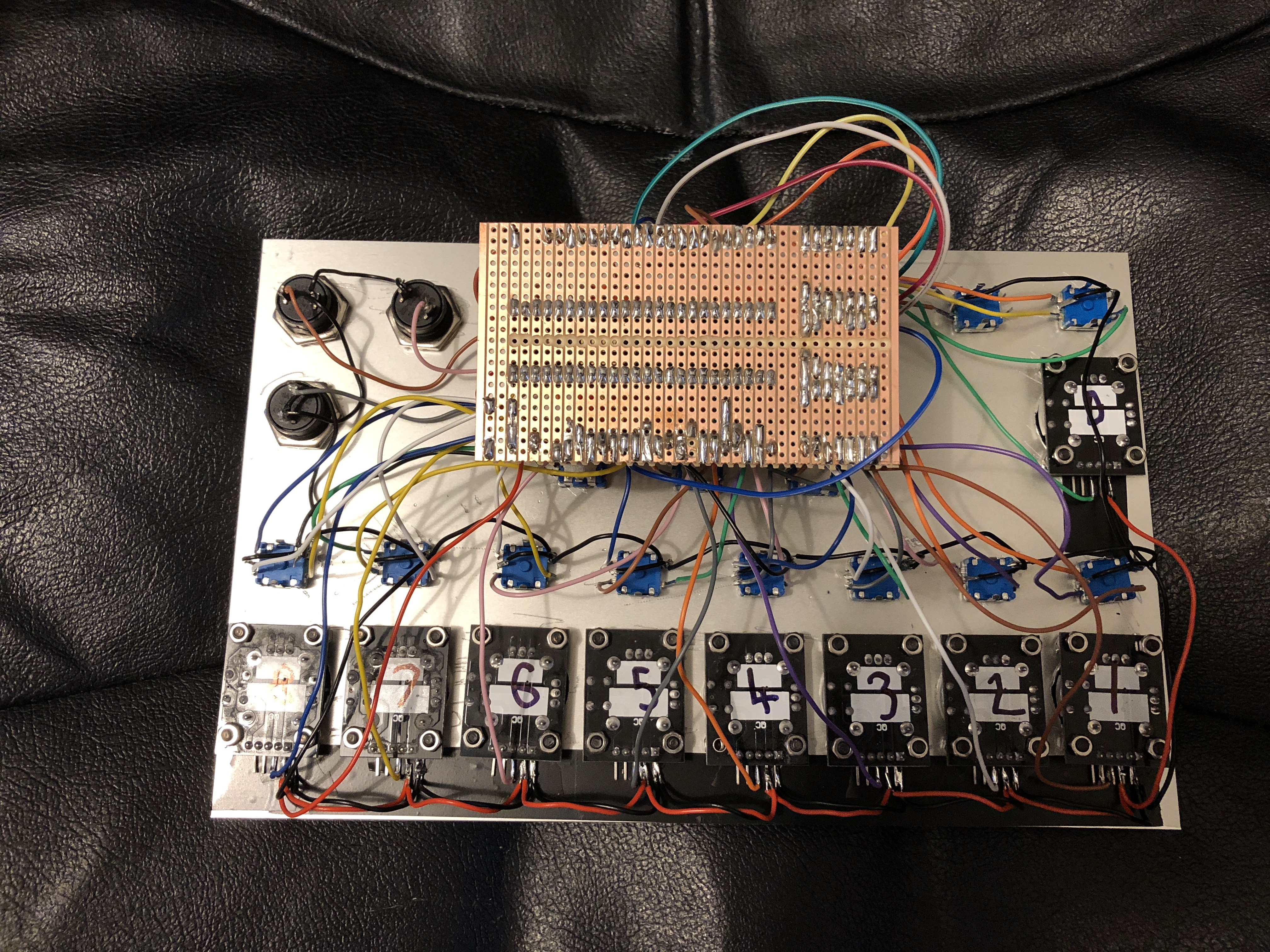
The completed electronics.
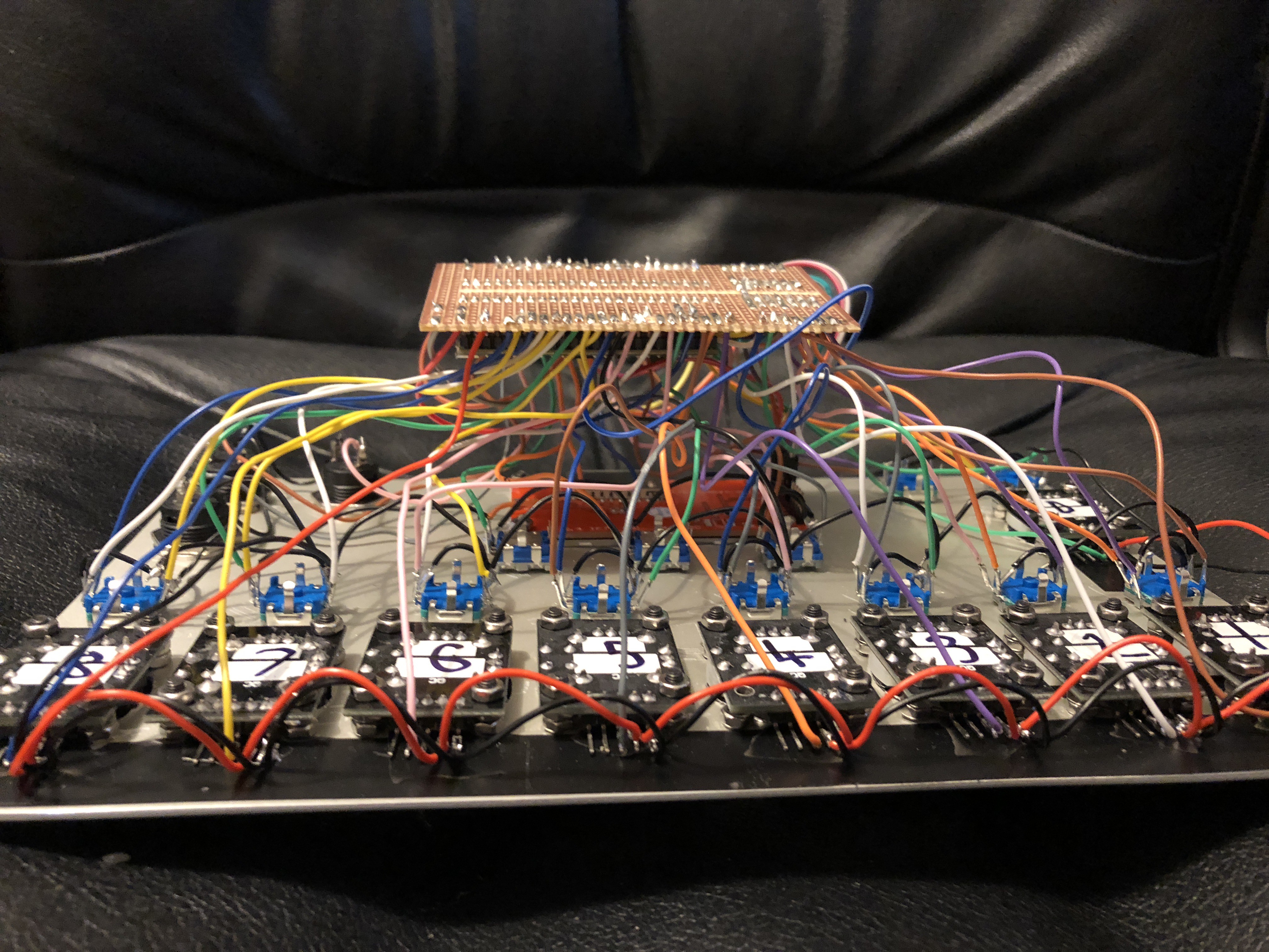
The mess of wires.
Discussions
Become a Hackaday.io Member
Create an account to leave a comment. Already have an account? Log In.