 Mark Omo
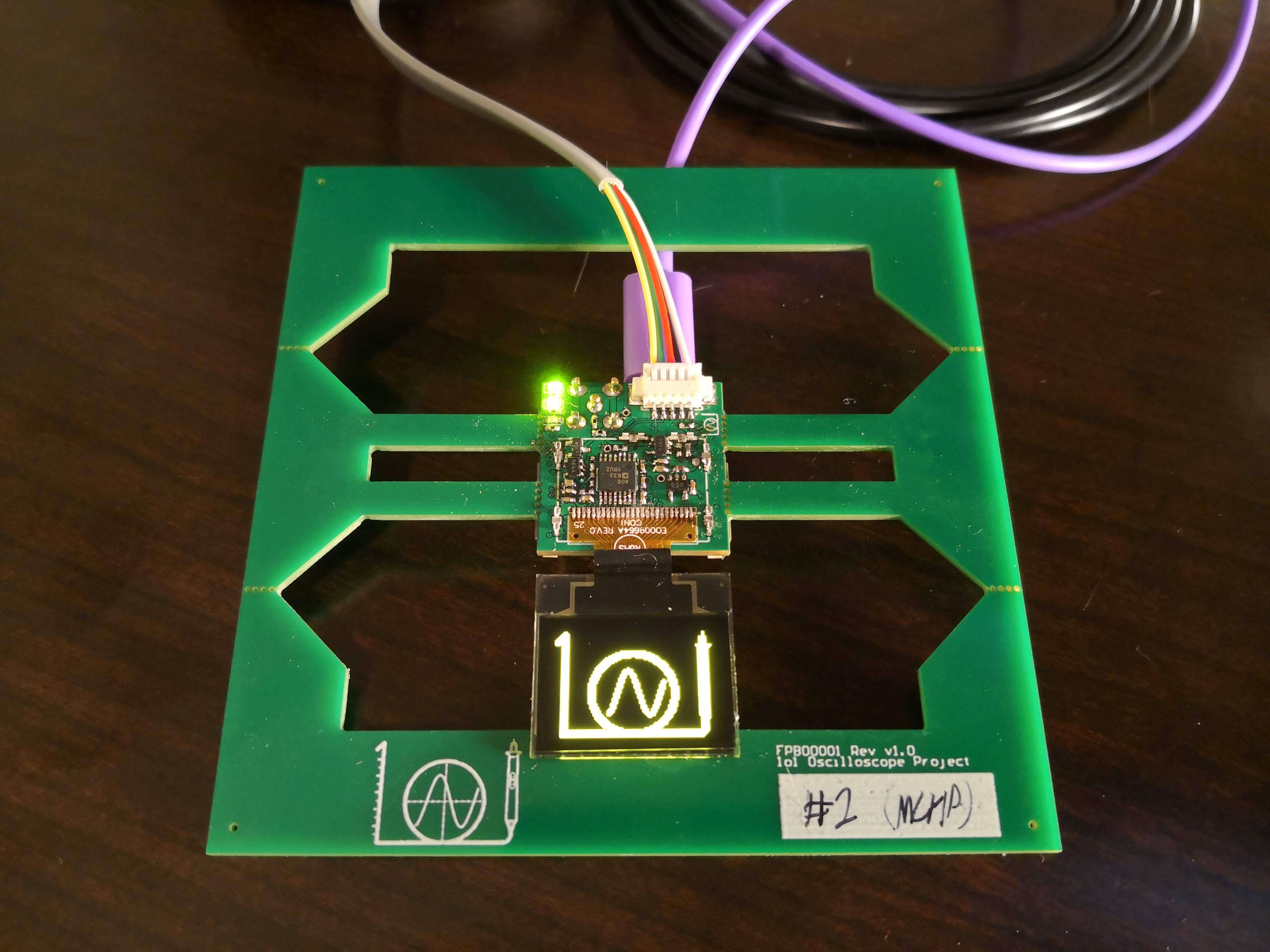
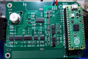
This project is designed around a PIC32MZ EF processor. We use its internal ADCs in an interleaved mode in order to get the full 20Msps. We have found that in practice we are able to achieve approximately 1MHz of bandwidth.
Finished unit:
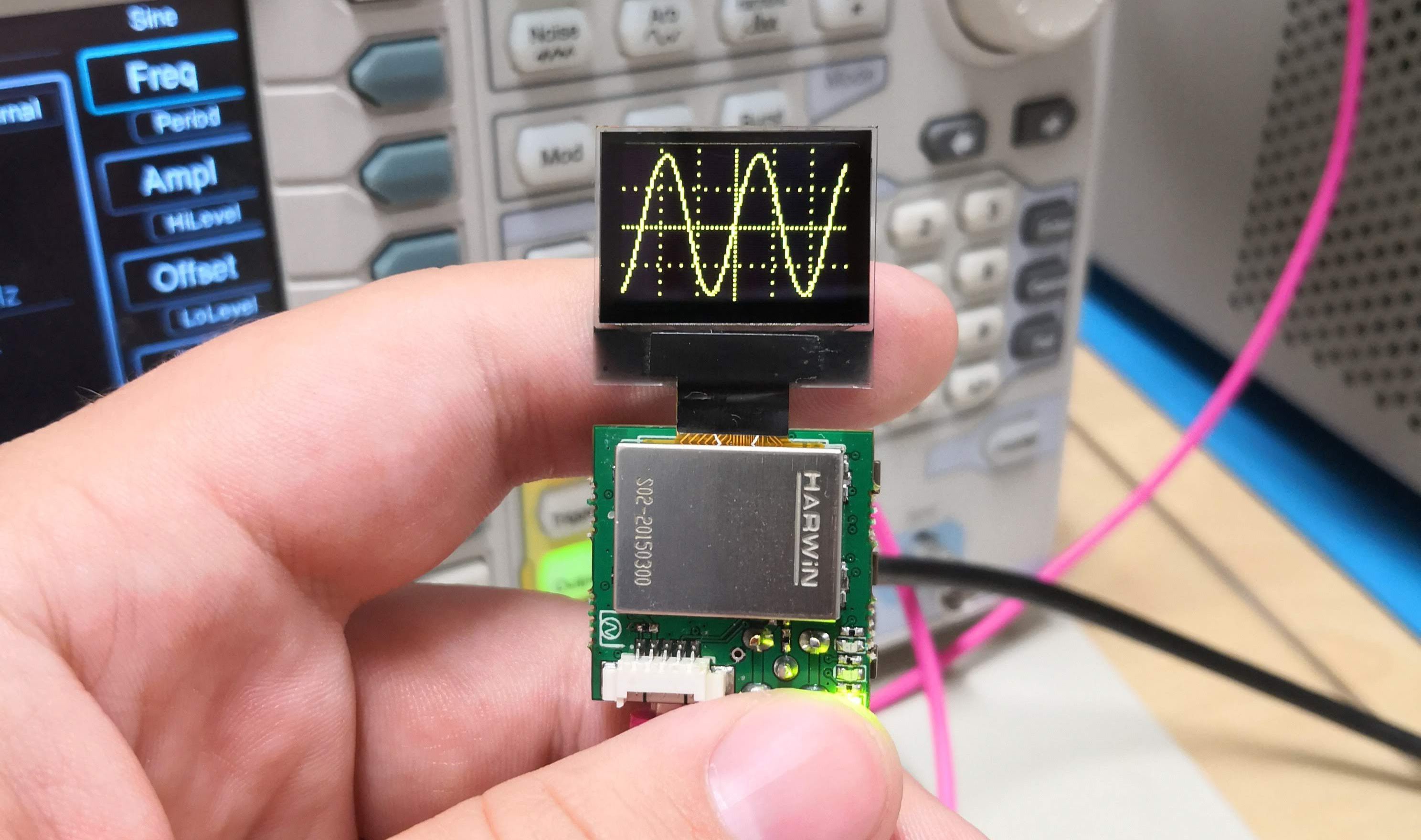
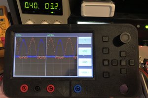
Demo Video:
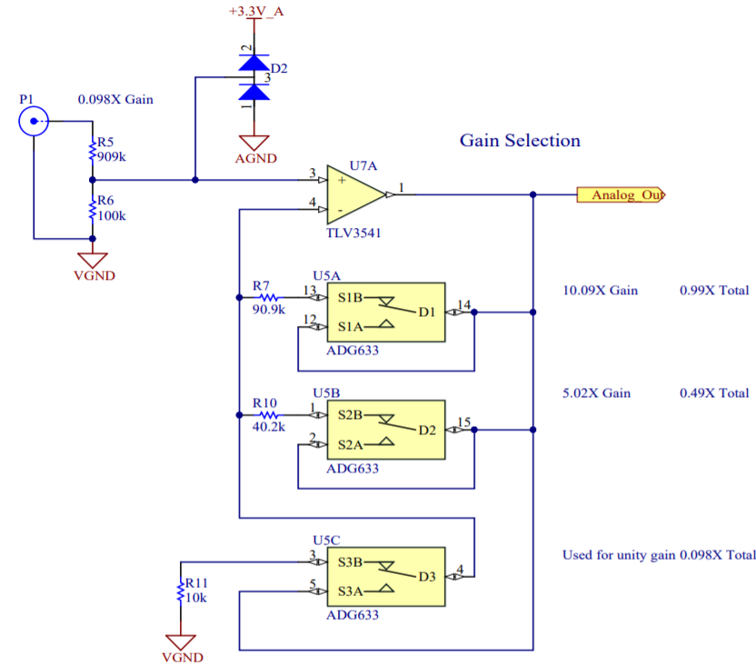
System overview:

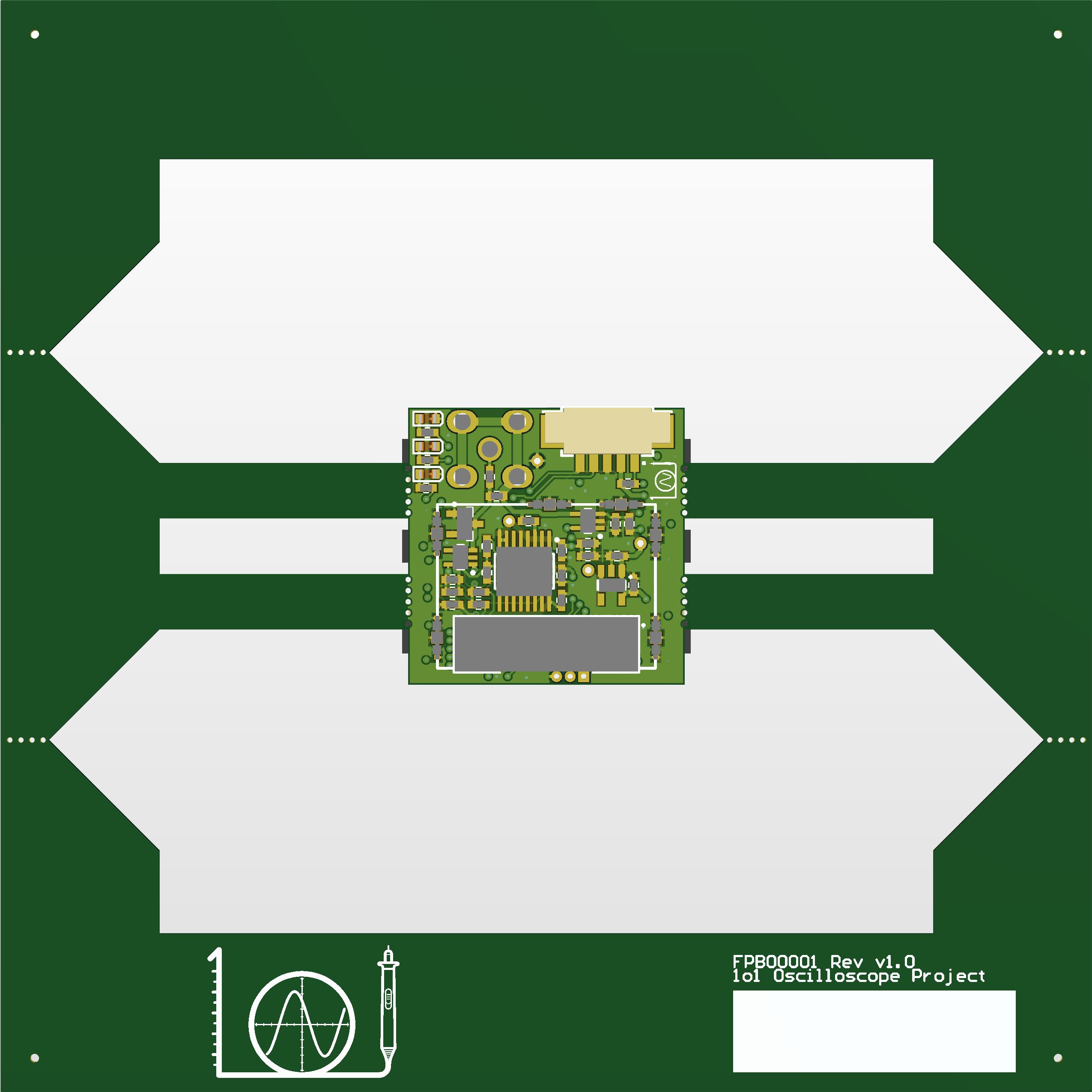
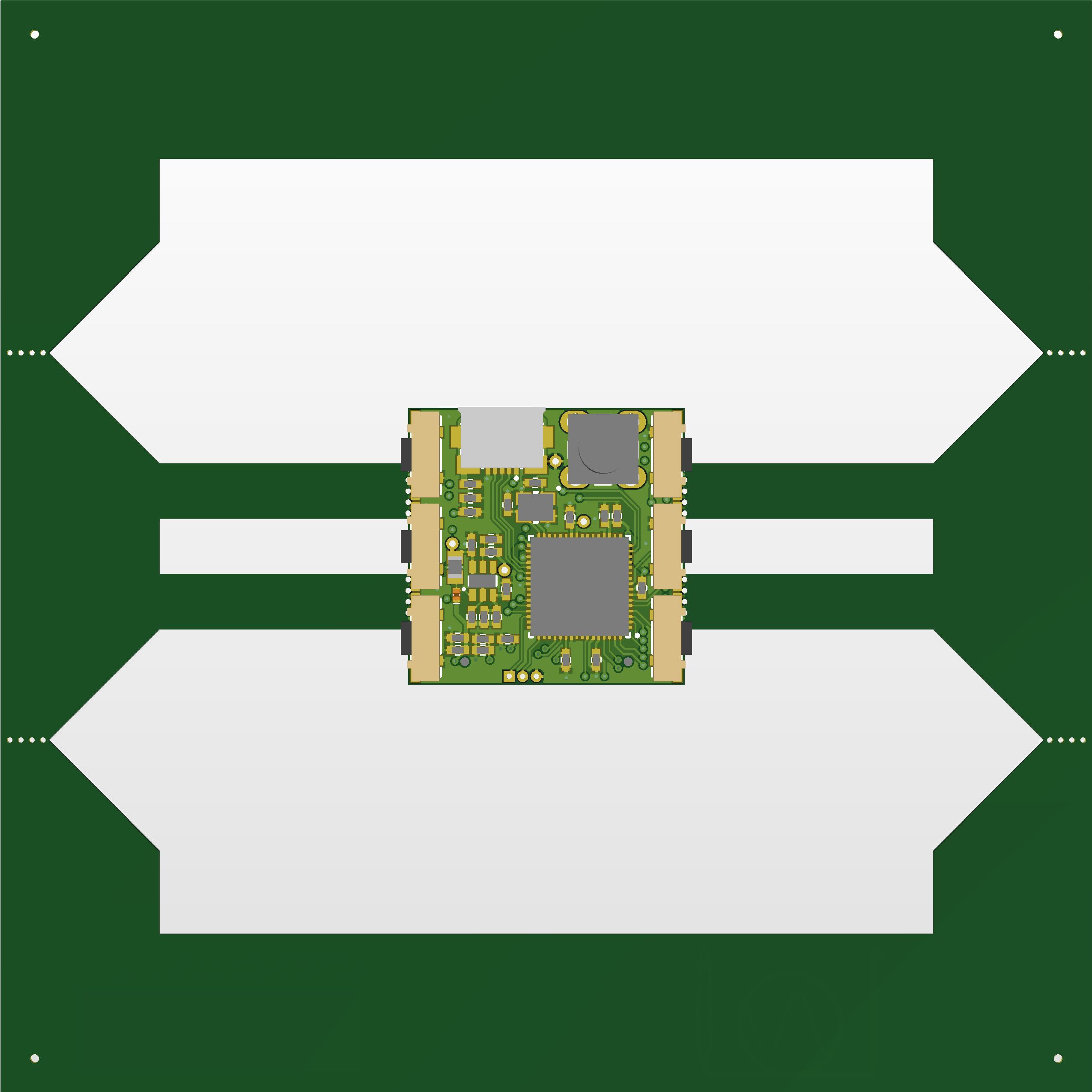
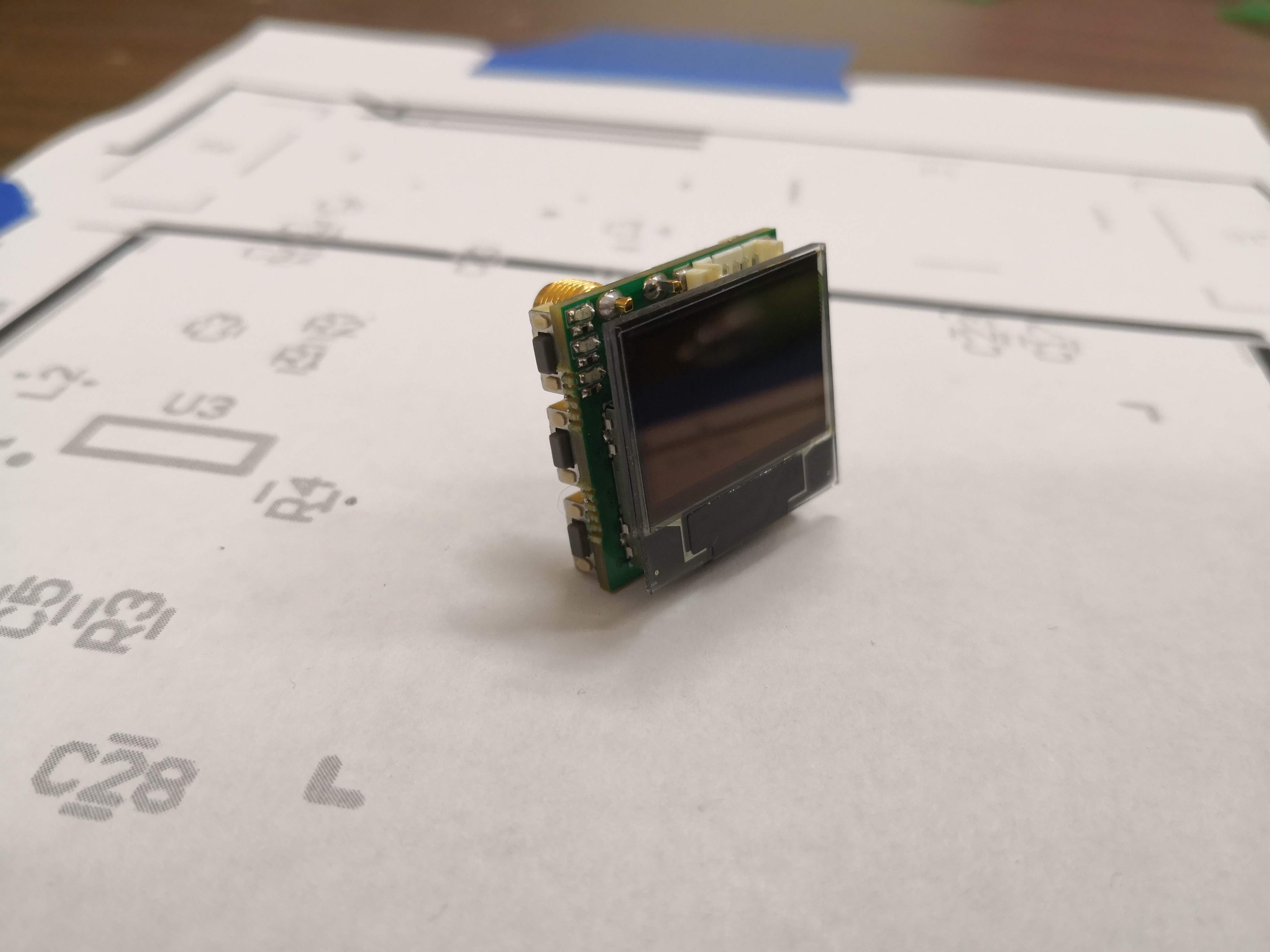
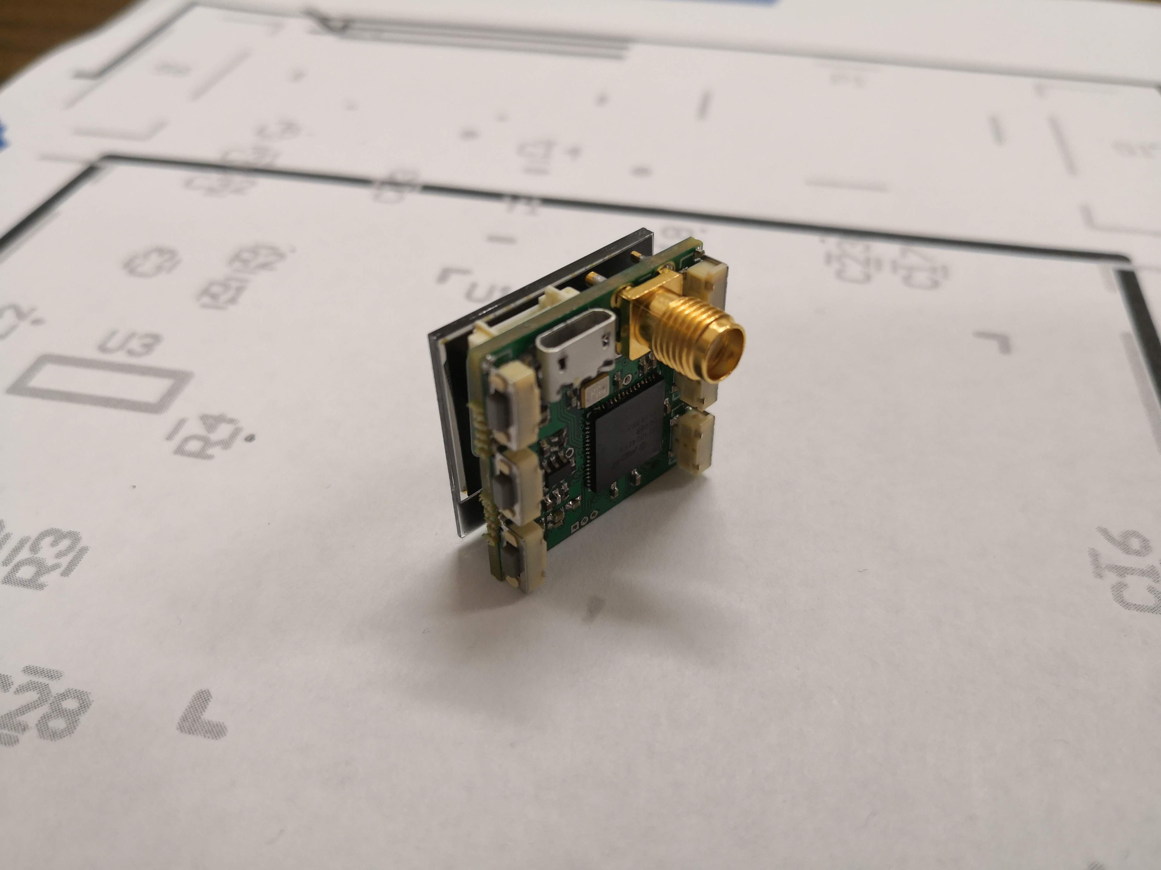
Here are some glamour shots of the finished PCB Layout:


 NNNI
NNNI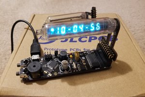
 sjm4306
 Jianjia Ma
I thought I've seen everything on an inch², but this really is fantastic. The "screen included" thing is just awesome. Not too practical resolution-wise but a nice touch anyway.
Wish you the best for the contest!