 Jan Bert
The ESI Juli@ audio interface provides a single stereo input and output. Simply providing TRS connectors to the backside of the enclosure for the audio interface isn't enough. A mixer is needed to combine the signal of my Nord stage and Access Virus kb with the VSTiBox output, and send only one stereo mix to the mixer table. When playing in more professional bands this is not an issue because the sound guys like to receive multiple separate synth channels so they can can make their own mix, but in the places I perform it is better to do the mixing myself. Also a headphone output is needed. A monitor input with signals from the rest of the bandmembers is routed to the headhpone output only. I made the following design of the audio routing for the mixer before diving into schema and pcb design:
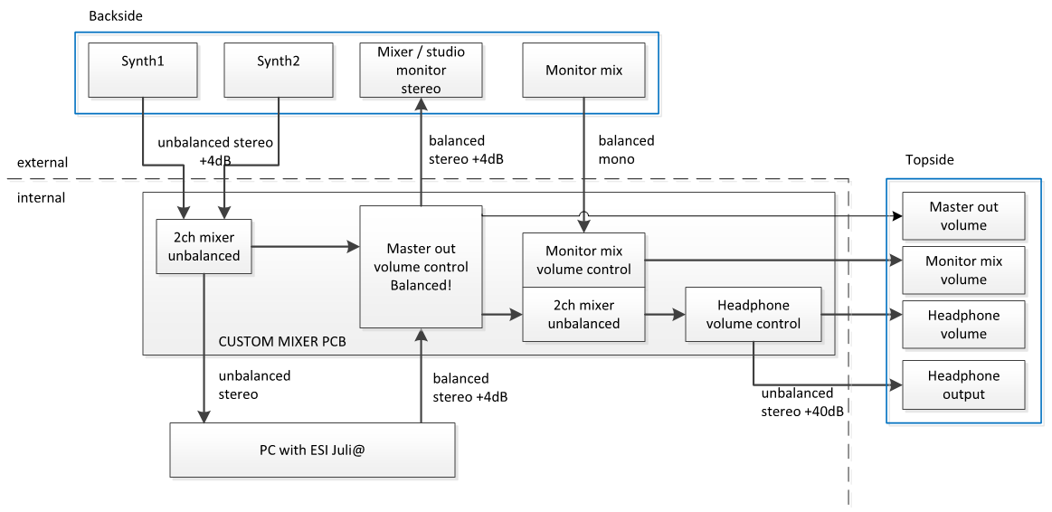
In the final design the headphone output has moved to the backplane. Also the audio to the Juli@ is balanced. This is the first audio design I have ever made, but I got some help from an expert for which I am very thankful. I tried to design it reasonably HIFI, with no sacrifice on cheaper parts.
I did some research on good sounding opamps and settled for the LME49740 for quad and LM4562 for dual opamps. Generally I chose the feedback resistors to be <= 10k, and lower when possible, with a matching capacitor to create a low pass filter with -3dB at 150kHz just to prevent high frequent ringing.
The power supply consists of the TPS7A4501 positive and TPS7A3301KC negative utra low noise linear regulators. Both have a 220uF low ESR tantalum buffer cap. I designed the power stage for +/-12Vdc input, and +/-10Vdc output, so all the opamps and the headphone amp operate on +/-10Vdc.
The headphone amp is made of a pair of LME49600's, each with their own servo circuit for removing a DC component.
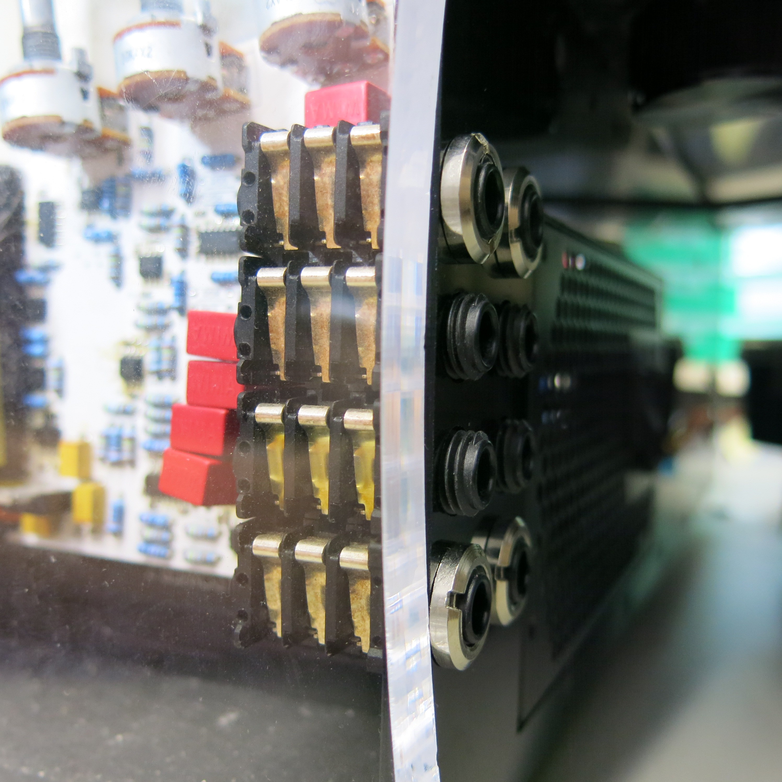
The output of the volume control potmeters have a 100k pull down to prevent a cracking noise when turning them. I chose audio tapered potmeters that fit on angled side of the pcb. The pcb has the same angle as the top side of the case. The back side contains 4 dual row stereo Neutrik connectors for in- and outputs which are mounted in place by a nut. The line inputs are routed through 4.7uF polyethylene WIMA caps (MKS2B051001N00MSSD) for decoupling which according to some HIFI forum posts sound best. For the same reason I have used metal film caps and through-hole resistors. That didn't bother my because I had to solder the PCB by hand anyway. It also made routing easier I think, because all the through-hole components create a kind of 3rd board layer.
During assembling and testing I discovered a few mistakes:
1. The footprint of the caps was wrong, but this was easily solved.
2. I made a mistake in copying the servo circuit for the LME49600 from its application note, which resulted in a damaged earphone. Fortunately not a damaged ear!
3. If I recall it correct there is an error in the gain of the input stage from the Juli@ (L+R balanced input). But I still have to figure that one out. For now I can sufficiently adjust the level with the volume potmeter.
4. There is a mistake in one of the mounted resistors; the left and right master output differ 3dB. I'll have to fix that too. All the sound guys I have worked with are annoyed that they have to unbind their stereo channel and use separate gains for left and right. If you read this: I'm sorry ;)
5. Noise. I can hear it very little, but I want it to be just dead silent. To figure this one out I have built a custom ultra low noise PSU instead of the +/-12Vdc coming from the ATX computer supply. I will discuss the PSU in a next log.
Discussions
Become a Hackaday.io Member
Create an account to leave a comment. Already have an account? Log In.