 Jan Bert
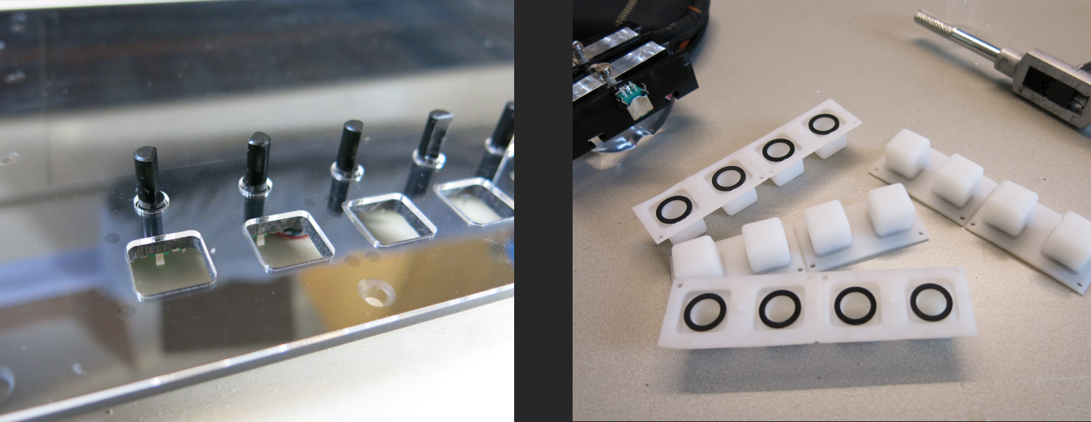
Below the LCD I needed 8 encoders in a row, with illuminated buttons below them. On the right side of the LCD, I also needed 8 illuminated buttons, but in a 4x2 configuration. Therefore I designed a custom PCB with 4 encoder inputs and 4 pads for silicon buttons each with an RGB led behind them. I bought the silicon buttons at Sparkfun.
The heart of the controller is a LPC1114 with the UART hooked up to a 4 pin header. Both sides of the PCB have the same header with power and UART RX+TX, so multiple controllers can be chained. The idea is that the controllers are hooked up in this way for receiving messages from the PC:
- PC TX => Controller 1 RX
- Controller 1 TX => Controller 2 RX
- Controller 2 TX => Controller 3 RX
- Controller 3 TX => Controller 4 RX
And for transmitting messages to the PC:
- Controller 4 TX => Controller 3 RX
- Controller 3 TX => Controller 2 RX
- Controller 2 TX => Controller 1 RX
- Controller 1 TX => PC RX
That means that controllers 1-3 are acting as a relay. Message are received in a queue on interrupt basis, and also transmitted on interrupt basis to offload the CPU in all the passing messages from the other controllers. The protocol supports an incremental ID which is assigned during initialization. This ID is used in each message to communicate with the correct controller.
The board also contains a SE95 for SPI temperature sensing. An OPA177S with two micro pots is added for reading the pitch wheel pots with an adjustable gain and offset, so the ADC can be used in almost its full range.
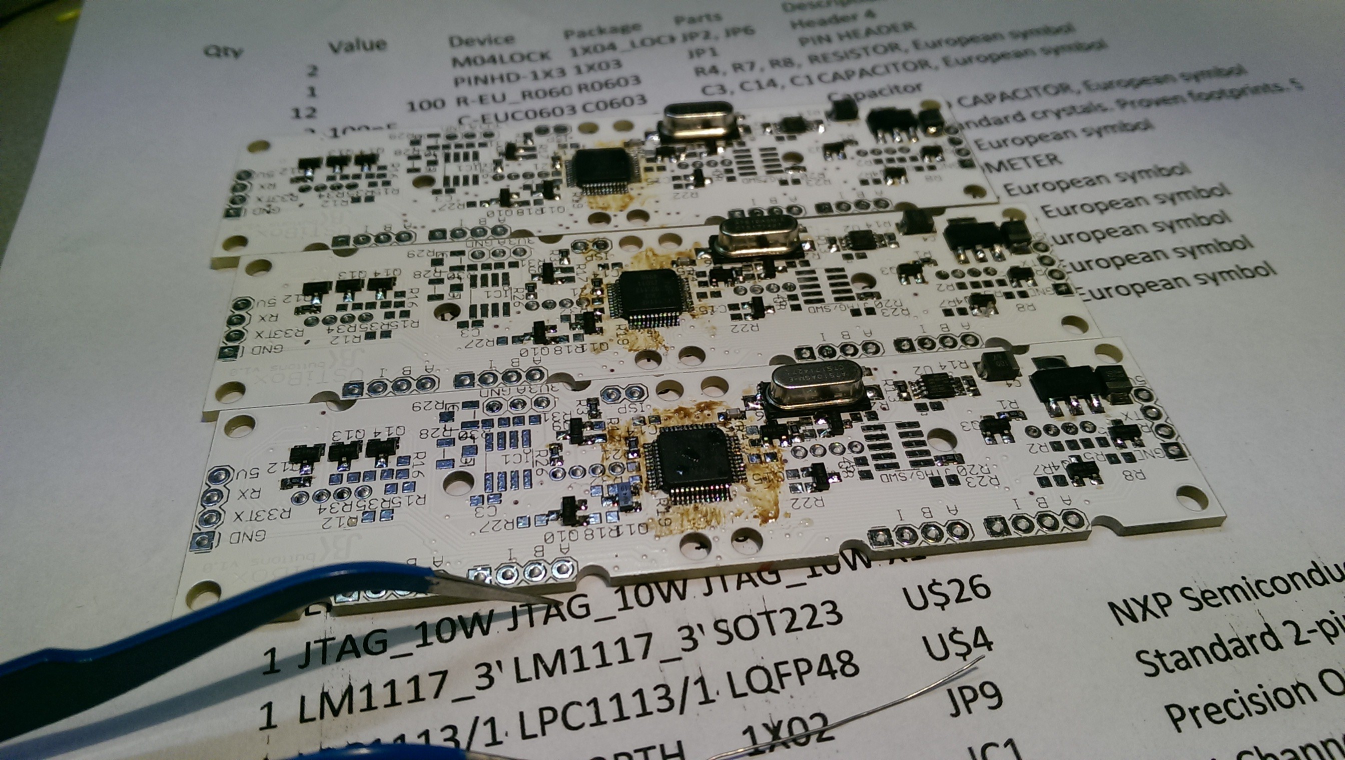
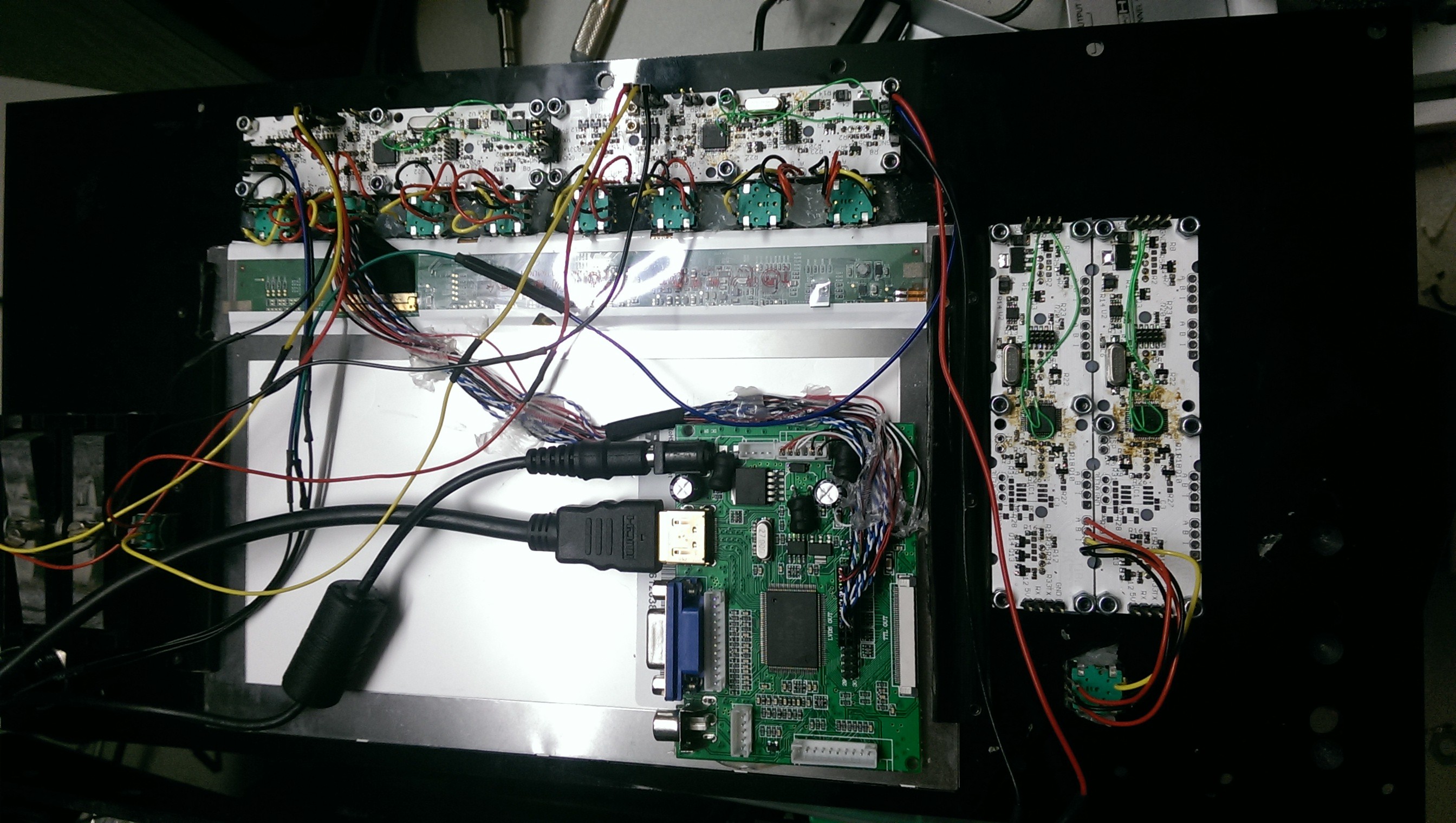
Unfortunately I made a mistake in the schematic and did not hook up the UART RX&TX to the microcontroller. That is why you can see the various thin green wires.
Discussions
Become a Hackaday.io Member
Create an account to leave a comment. Already have an account? Log In.