 T. B. Trzepacz
Having Mozzi and WS2812B libraries working and knowing which pins they had to use (due to use of PWM timers / SPI hardware) I could finally design a 1st draft PCB. It is kind of necessary to make a PCB to actually test the stylus keyboard part, anyway.
Fortunately, I'd finished up the rather complicated keyboard layout before I'd stopped working on the synth to make the pendants, so I didn't have to mess around with that again.
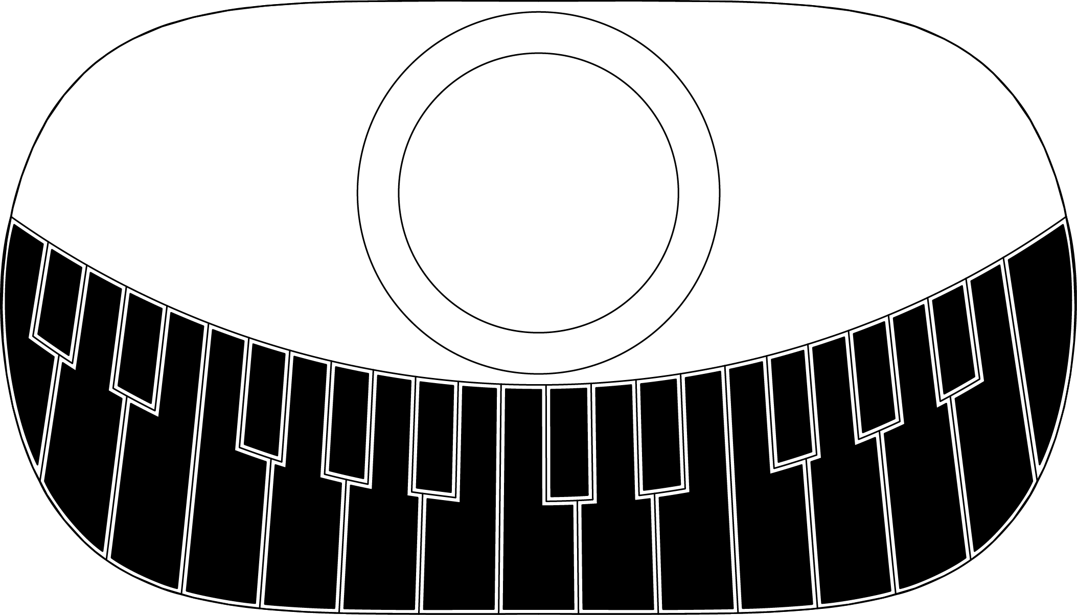
Getting KiCAD to turn a drawing into a filled footprint was tricky, but was finally accomplished by using the "Import Bitmap" option, otherwise known as "Bitmap to Component". It was pretty annoying that I had to take my nice vector art and convert to a bitmap before it could be turned back into vectors again, but despite some trickyness with DPI settings, I eventually got it.
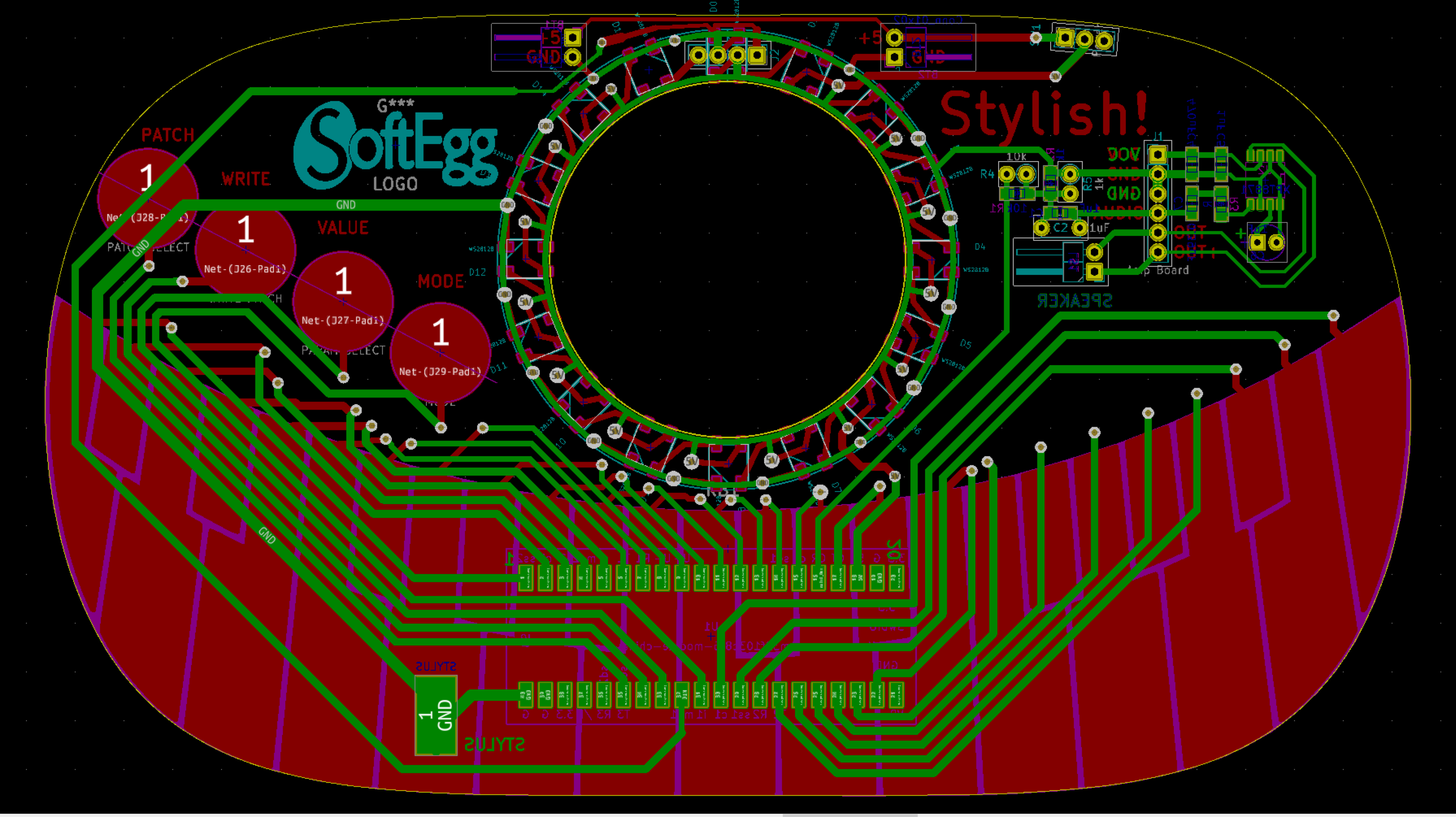
There are connectors on the board for attaching pre-manufactured LED ring and amplifier boards for easy kit building, but all of the SMD part footprints are there for inevitable factory assembly cheapness.
The STM32F103C8T6 processor is actually the complete development board, available from AliExpress for less than $2. It has to be mounted using two angled pin headers surface mounted on the back of the board, or else via a surface mount 40 pin socket and pin headers soldered to each board.
The speaker is mounted in the hole in the middle of the LED ring... somehow. It is attached via the pin header to the right of it, near the amplifier board.
The power switch is currently designed to be the same one used for the pendants, because I have some.
The stylus attaches via stranded wire to a large SMD pad on the bottom and back of the board. In this design it is tied to ground, and each pin is polled as input to detect which key/pad is touched. A future design might use shift registers to free pins, in which case, the stylus would need to be attached to an input pin.
This design uses ALL of the pins, so there is no room to add MIDI or rotary encoders, or potentiometers or anything like that, unless one started repurposing the programming and USB pins of the STM32, or change the keyboard to use shift registers or multiplexers.
Discussions
Become a Hackaday.io Member
Create an account to leave a comment. Already have an account? Log In.