Close
0%
0%

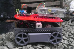
Wi-Fi Voice Controlled Robot with Google Assistant

Add voice control to your robot with the Google Assistant, Adafruit IO, and IFTTT!

Similar projects worth following
In this tutorial, I show you how to make a voice-controlled robotic tank controlled using a smartphone, Google Assistant, IFTTT, and Adafruit.io platforms. An ESP8266 Wemos D1 board was used in this project. It receives commands from a Wi-Fi network and control the speed of the motors. Other development boards might also be used (NodeMCU, Firebeetle, etc.), and the principles presented in this tutorial can be applied on other models of robots and other IoT gadgets.

I've previously designed a Blynk controlled robotic tank. It connects to a Wi-Fi network and receives commands from Blynk server.
https://hackaday.io/project/159910-wi-fi-controlled-robot-using-blynk-app

This time I decided to try a different way to control the same robot: voice commands. It might be u

ino - 4.99 kB - 09/01/2018 at 15:43

Download

View all 7 components

  • 1
    Tools and Materials

    The following tools were used in this project:

    • Solder iron and wire. The DC motors already came with wires soldered to its terminals... But it will eventually break and you might have to resolder it. So consider having a good solder iron and wire neaby.
    • EVA foam sheet (or other non-conductive material). The robot chassis I used in this project is made of aluminum, and circuit boards are installed on this metal parts. I used a layer of foam sheet between the boards and the metal plate to avoid possible short-circuits.
    • Double sided tape. It was used for glueing the foam sheets to the circuit boards, and for the installation of the H-Bridge modue.
    • Scissors, for cutting some foam sheet rectangles.

    I used the following hardware parts for my project:

    • Wemos D1 ESP8266 dev board (link). Wemos D1 board is really easy to use and program with Arduino IDE. It has the same footprint of and ordinary Arduino Uno! This way most of Arduino shield will also work with this board. It has built-in Wi-Fi module, so you can use it in a variaty of projects.You can also use other ESP8266 based boards (link / link).
    • L298N dual channel H-bridge module (link). This module allows the 3.3V signals from the Wemos (or an Arduino) to be amplified to the 12V needed for the motors.
    • DIY Robot Chassis Tank (link). This awesome kit has with everything you need to built a tank: two DC motors, gears, tracks, bolts, nuts, etc. It already comes with the tools need for assembling the chassis, which is great for beginners!
    • 18650 3.7V batteries (x3) (link). I used to power the whole circuit. This tank uses 12V motors. I used three 3.7V batteries in series for powering them.
    • 3S 18650 battery holder (link). It can hold three 18650 batteries in serie, and can be easilly be attached to the back of the tank.
    • 18650 battery charger (link). Your batteries will eventually run out of power. When that happens, a battery charger will come to your rescue.
    • Jumpers (link). I used 6 male-female jumpers for signals between the h-bridge an the Wemos, and 2 male-male jumpers for 5V and Gnd. You might need more if you plan to add some sensors.
    • Micro USB cable. You'll need this for uploading your code. Most of the boards already come with its own cable.

    The links above are only a suggestion of where you can find the items used in this tutorial (and maybe support my future tutorials). Feel free to search for them elsewhere and buy at your favorite local or online store.

  • 2
    Assembling the Robot

    The first part of this project was the assembly of the robot structure.

    In previous projects I developed the structure of my own robot, using easily accessible materials (without the need for complex tools, 3D printers or laser cutting machines). You can find this project in the link below:

    https://hackaday.io/project/25694-widc-wi-fi-controlled-fpv-robot

    This time I decided to give a chance for a robotic kit obtained from an online store. You can find a link to the robot chassis at the following link: http://bit.ly/2ycI8fP. If you're looking for a kit, I think it's a good option!.

    At first it seemed that the assembly would be complex or that I would run into problems like the lack of parts (given the amount of parts that make up the kit). But this kit really surprised me! All the pieces seem to me of good quality, and several spare parts accompanied the kit. Thus, a screw lost underneath the workbench won't make it impossible to carry out your project, which I found to be excellent (especially after losing a couple of screws).

    Another positive point is that all the tools needed to mount the robot are included in the kit (a couple of Allen wrenches and the screwdriver). I believe this makes the kit excellent for starters who doesn't have lots of tools!

    As a negative aspect I would highlight the lack of documentation. The robot's assembly manual (a spreadsheet file in Chinese) is not extremely user friendly, and there isn't a lot of tutorials online for that tank. And so I decided to document the process of assembling my robot in the video above! Another point of attention concerns the material of the robot structure. The base is entirely made of aluminum, which can cause some short circuit if the pins of the printed circuit boards touch the frame.

    There are other online kits that you can use. You can even maker your own structure, as I described above.

  • 3
    Wiring Up the Circuit (Wemos D1)

    In the video above I show you how you can assemble the electronics in the robot structure.

    A power pack made of three 18650 batteries was installed on the back of the robot. It provides 11.1V (3 x 3.7V) to the robot. That's enough to power the 12V DC motors.

    A L298N dual channel H-bridge was used for the control of the motors. It receives some 3.3V signals of the Wemos board, and provide higher voltages for the motors. It also allow the motors to run in both directions, depenting on the combination of those input signals.

    Each device was connected according to the schematics.

    Follows a list of the pins you'll need to connect:

    Wemos D1 inputs/outputs:

    • Digital pin D3 (GPIO5) => H-Bridge ENB pin
    • Digital pin D4 (GPIO4) => H-Bridge IN4 pin
    • Digital pin D5 (GPIO14) => H-Bridge IN3 pin
    • Digital pin D6 (GPIO12) => H-Bridge IN2 pin
    • Digital pin D7 (GPIO13) => H-Bridge IN1 pin
    • Digital pin D8 (GPIO0) => H-Bridge ENA pin
    • 5V pin => H-Bridge 5V pin
    • Gnd pin => H-bridge Gnd pin

    H-Bridge inputs/outputs:

    • ENB pin => Wemos D3 pin
    • IN4 pin => Wemos D4 pin
    • IN3 pin => Wemos D5 pin
    • IN2 pin => Wemos D6 pin
    • IN1 pin => Wemos D7 pin
    • ENA pin => Wemos D8 pin
    • 5V pin => Wemos 5V pin
    • Gnd pin => Wemos Gnd pin
    • Gnd pin => Battery pack negative wire
    • 12V pin => Battery pack positive wire
    • OUT1 => Right motor negative wire
    • OUT2 => Right motor positive wire
    • OUT3 => Left motor positive wire
    • OUT4 => Left motor negative wire

View all 11 instructions

Enjoy this project?

Share

Discussions

Pereira wrote 03/26/2019 at 20:30 point

error : “command” not defined

With respect to the line in the code .. 

command->onMessage(handleMessage) ;

  Are you sure? yes | no

Similar Projects

Does this project spark your interest?

Become a member to follow this project and never miss any updates