Close
0%
0%

MEP LED

My E(I)llumination Project - and I can't spell

Similar projects worth following
Caution! Do NOT try this at home... unless you know what you are doing. This project is done by a professional engineer in a closed lab. Seriously, dealing with AC mains is dangerous!

My entry to the Macrofab Engineering Podcast contest - Blink an LED. I am going to blink 2 LEDs directly from AC power with just two resistors. Simple and dangerous. Non of the 3 categories really fit for this project, so I pick the 'Pragmatic Blinky' one because it is useful in a way that it uses very few components and AC is available (almost) everywhere. And I hope for the 4th category because there will be much more useful entries. :-)

The primary goal, a blinking LED is achieved by simply using big enough resistors as current set for the LED and connect them to AC line voltage. 2 LEDs in reverse to each other are used for:

  1. utilize both half waves of the AC line.
  2. not risk the full AC voltage in reverse across a single LED.

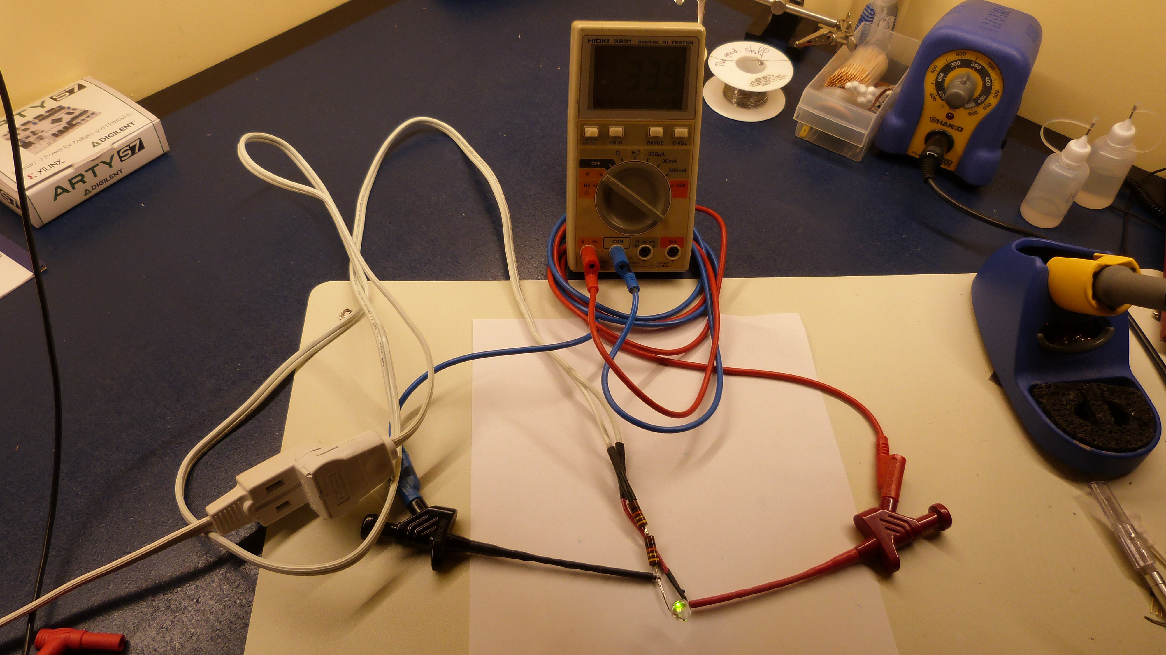
Here in Canada we have 120V, 20KOhm deliver a nice 6mA to a red and green LED. To be really safe, 2 resistors are used. And to be even safer, the initial test was done outside on good solid Nova Scotia bedrock, in case the LED would blink only once but violently bright.

Here is the schematic:

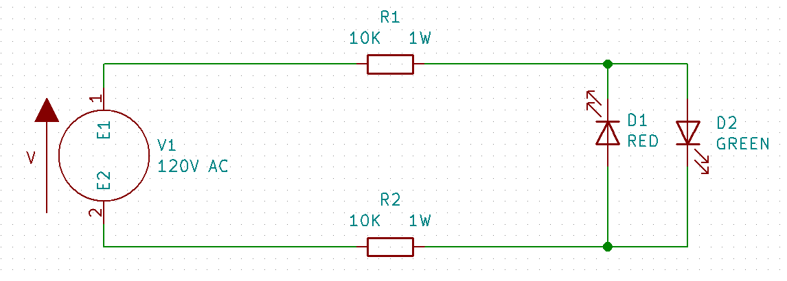
More pictures in the gallery show the 120V AC across the whole circuit and ~2V across the LED with either red or green LED on. Theory and practice agree for once. The part list will show parts available at Mouser to recreate this setup.

Cheers and Good luck.


SCH_MEP-LED.pdf

Schematic

Adobe Portable Document Format - 14.03 kB - 09/05/2018 at 00:14

Preview
Download

  • 1 × LED green 10mm TH 593-VAOL-10GDE4
  • 1 × LED red 10mm TH 593-VAOL-10GAT4
  • 2 × Resistor 10KΩ 1W TH 71-CPF110K000FKEE6
  • 1 × AC power cord 562-221001-08

  • 1LED 1 resistor

    MagicWolfi09/08/2018 at 03:09 0 comments

    I managed to cut the component count by 50%. The circuit does not explode when I use only 1 LED and 1 resistor and the LED is on. So, still lacking a high speed camera, I cannot record the blinking LED. The multimeter shows a weird 33.9V AC because it cannot decide between -2V AC or +120V AC. And yes there are 2 resistors in the circuit, but they are in series and it is up to the student to reduce this to a single one. ;).

    Cheers to a very tough LED.

View project log

  • 1
    Solder LEDs

    Solder LEDs together:

    - Anode red to Cathode green

    - Cathode red to Anode green

  • 2
    Solder resistors

    Solder a 10KΩ 1W resistor to each LED solder joint.

  • 3
    Solder power cord

    Solder the other side of each resistor to one of the wires of the power cord.

View all 6 instructions

Enjoy this project?

Share

Discussions

Guy Thomas wrote 09/17/2018 at 20:28 point

I like that line about one violently bright blink!  "The project worked, but only once and for a very short time.  After that there was smoke."

  Are you sure? yes | no

MagicWolfi wrote 09/18/2018 at 02:40 point

Thanks, man. @TCurrentSource (one of the judges for the contest) had a nice video clip on his tweet thing to this topic.

https://twitter.com/TCurrentSource/status/1037796344474345472

  Are you sure? yes | no

Gerben wrote 09/04/2018 at 18:13 point

I'm sure Parker and Stephen will like this one.

  Are you sure? yes | no

MagicWolfi wrote 09/05/2018 at 00:22 point

Thank you. That is the master-plan. And world domination.

  Are you sure? yes | no

Similar Projects

Does this project spark your interest?

Become a member to follow this project and never miss any updates