 Hulk
HulkDIY - LAN CABLE TESTER
There is nothing worse than running your drops only to realize that you have a fault in one of the cable runs. The best approach is to get it right in the first place by using a "LAN Cable Tester". Sometimes, cables can also tear because of poor material quality or bad installation or sometimes they get gnawed by animals.
In this project, I am going to make a LAN cable tester with just a few basic electronics components. The entire project, excluding the battery cost me just a bit over $3. With this tester we can easily check RJ45 or RJ11 network cables for their continuity, sequence and if they have a short-circuit.
Step 1: Hardware Requirement

For this project we need:
1 x Perfboard
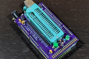
1 x Arduino Uno/NANO whatever is handy
2 x RJ45 8P8C Ethernet Ports
9 x LEDs 9 x 220Ohms Resistors
9 x 1N4148 Fast Switching Diodes
1 x SDPD Switch
1 x 555 Timer IC
1 x 4017 Decade Counter IC
1 x 10K resistor
1 x 150K resistor
1 x 4.7 uF Capacitor
1 x 18650 Battery
1 x 18650 Battery Holder
1 x TP4056 Module for charging the battery
few connecting cables and general soldering equipment
Step 2: Logic

A network cable consists of 8 wires plus sometimes a shield. These 9 connections must be tested one after the other, otherwise a short between two wires or more can not be detected. In this project I am only testing the 8 wires however just by doing a little bit of modification you can test all the 9 wires.
The sequential testing is done automatically by multi-vibrator and a shift register. In principle the circuit just is a running light with the LAN cable in between. If one wire is disconnected, the corresponding LED will not light up. If two wires have a short-circuit two LEDs light up and if wires are interchanged the sequences of the LEDs will be also interchanged.


The 555 Timer IC operates as a clock oscillator. The output on pin 3 goes high every second causing the shift.
We can also achieve this by adding an Arduino instead of the 555 IC. Just send a digital high followed by a digital low every second using the blink example from the Arduino IDE. However, adding an Arduino will add to the cost but will also reduce the complexity of soldering.

The signal from the 555 IC or Arduino clocks the 4017 decade counter. As a result, the outputs on the 4017 IC are switched sequentially from low to high.
The clock pulses generated at the output of IC 555 timer on PIN-3 is given as an input to IC 4017 through PIN-14. Whenever a pulse is received at the clock input of IC 4017, the counter increments the count and activates the corresponding output PIN. This IC can count upto 10. In our project we only need to count upto 8 so the 9th output from Pin-9 will be fed to the Reset Pin-15. Sending a high signal to Pin-15 will reset the counter and it will skip counting the rest of the numbers and will start from the beginning.
Step 3: Assembly Without Arduino

Lets start by connecting the pins of the 555 timer IC .
Connect Pin-1 to ground. Pin-2 to Pin-6. Then connect the 10K resistor to the +ve rail and the 150K resistor to the intersection of Pin2 and Pin6. Connect the capacitor to one end of the intersection and the other end to the ground rail. Now, connect the Pin-7 to the intersection of the 10K and 150K resistors creating a voltage divider. Then, connect the output Pin-3 of 555IC to clock pin of 4017IC. Next, connect the Pin4 to Pin8 and then connect them to the +ve rail. Add the switch to the +ve rail followed by the on/off indicator LED.
After connecting all the pins of 555 IC its time for us to connect the pins of 4017 IC. Connect Pin-8 and Pin-13 to ground. Short Pin-9 to the Reset Pin-15 and Pin-16 to the +ve rail. Once all the above pins are connected its time for us to connect the LEDs to the circuit. The LEDs will be connected from pin 1 to 7 and then on pin number 10 as shown in the diagram.
Each LED will be connected in series with a 220Ohm resistor and in parallel with a 4148 fast switching...
Read more »
 Mild Lee Interested
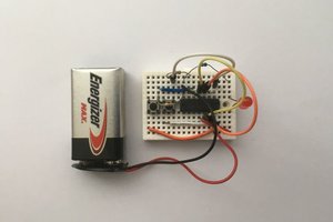

 Eric Ljungquist