 Alex
AlexBased on this board, I made several training projects. I'll post them a little later, as soon as I figure out how.
0%
0%
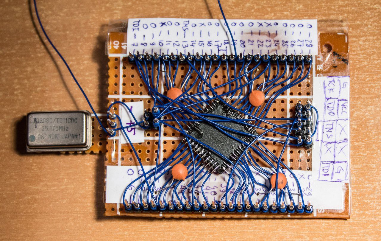
The FPGA evaluation board - Frankenstein
In old PCB's i found a low-capacity FPGA(CPLD) - EPM7064. I decided to make a small evaluation board.
Become a Hackaday.io member
Already have an account? Log in.
Just one more thing
To make the experience fit your profile, pick a username and tell us what interests you.
Pick an awesome username
hackaday.io/
Your profile's URL: hackaday.io/username. Max 25 alphanumeric characters.
Pick a few interests
Projects that share your interests
People that share your interests


 ASHUMHRPROJECTS
 Dave's Dev Lab
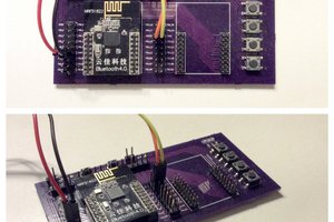
 Lukasz
 Christoph
Frankenstein is pretty close to me. I am glad that you raise this issue in your article. I can tell you that last week I needed to do an essay on the subject of Frankenstein and what I did, I turned to the guys for help https://blablawriting.com/essay-examples/frankenstein It's good that there are some really good quality essay examples for all kinds of topics.