 Alexander
Take a look at Part 1 of this tutorial series:
| ESP8266 SDK Tutorial | Learn how to use the ESP8266 SDK. This is what the pros use! |
| ESP8266 Lua/NodeMCU Tutorial | A look at the NodeMCU Lua interpreter for the ESP8266. Learn how to get to Blinky! |
| ESP8266 Arduino Tutorial | Use the Arduino IDE to simplify development and get up to speed very quickly! |
And here's the links to the other tutorials in Part 2:
| ESP8266 SDK Tutorial (You are here) | Looking at using the linker to get PWM, and the included I2C libraries |
| ESP8266 Lua/NodeMCU Tutorial | Using PWM and I2C with Lua! |
| ESP8266 Arduino Tutorial | Using the Wire library for I2C, and AnalogWrite for fading! |
Links to Part 3:
| ESP8266 SDK Tutorial | Using MQTT to develop an IoT device |
| ESP8266 Lua/NodeMCU Tutorial | Using the NodeMCU MQTT module to communicate with a cloud data service |
| ESP8266 Arduino Tutorial | We use the simpler, more widely available HTTP protocol to log data to the cloud |
Getting Help
If you run into trouble while following these tutorials, you have a few different options:
- Ask in the discussion area below the article
- Join the ##esp8266 channel on Freenode IRC and ping me (MrAureliusR) or ask anyone who is in there
- Post on the ESP8266 Community Forums (note it can take a while to get a response!)
- Send me a private message here on Hackaday
SDK Part 2: PWM and I2C
What is PWM?
Pulse-width modulation (PWM) is a method to control the average voltage of a signal without using analog means, such as a digital-to-analog converter (DAC) or digital potentiometer. By producing a square wave and changing the duty cycle, we control the amount of power delivered. The duty cycle is the ratio between the time the signal is in the high state and the low state. Think of it like an integral -- we are changing the area under the curve, which is equivalent to power. Take a look at this diagram:
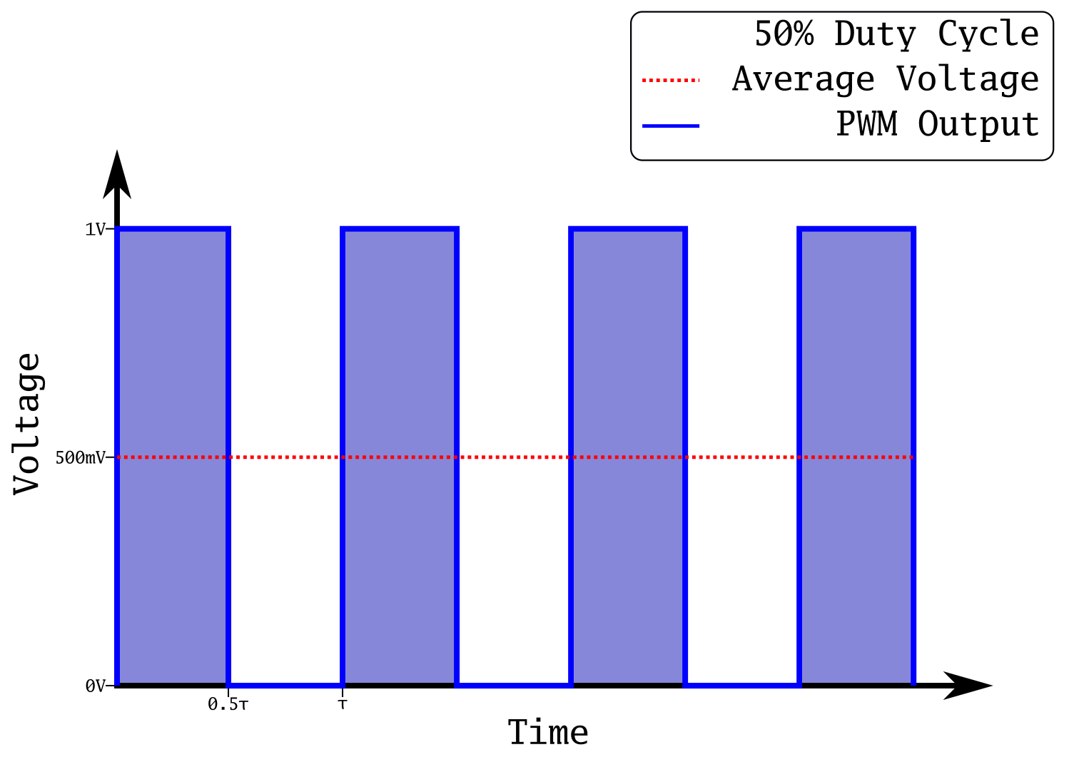
This is a plot of a square wave at 50% duty cycle. This means it spends half of its period (τ) in its high state, and the other half in its low state. In the case of this output, that means 1 V and 0 V respectively. The power transmitted is the integral of this plot, which is represented by the blue shading under the curve. Notice how that area is equal to the area during the low state; this is how we know it's at 50%. This has the effect of producing an average voltage of 500 mV. If we were to produce an analog output at 500 mV, and take the integral, it would be equal to the integral of this PWM output. This is extremely useful, as creating square waves is simple with a microcontroller, whereas creating analog voltages requires many extra components.
What happens if we reduce that output to 30%?
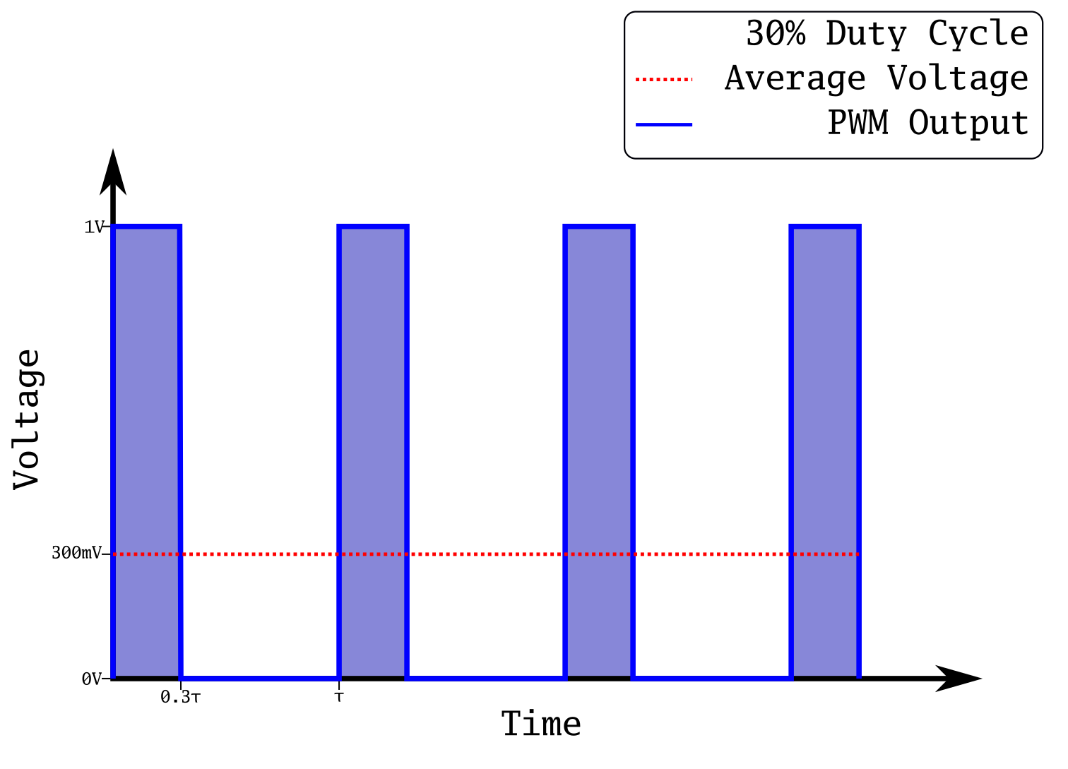
Now the on state is only on for 30% of the time. Our average voltage has now dropped to 300 mV. We have reduced the power sent out of our microcontroller pin just by changing the duty cycle of a square wave! If you are into math, you can prove that the analog voltage and the square wave are equivalent:
T is the period in seconds, and sgn() is the sign function. It's a simple way to get a perfect square wave on a plot. The integral of 0.5 from 0 to 20 is exactly 10, and the integral of the square wave will be almost exactly 10 as well. They will get closer with a faster period, and with more cycles. If you were to integrate to infinity, they would be exactly the same.
This is a common technique to control things like LED brightness, servo position, and buzzers. We are going to use it to fade an LED in the tutorial section below.
A quick side note about brightness of LEDs and PWM. The way human eyes respond to light is non-linear. Especially when LEDs are near the limit of their brightness, adding more current has a very small effect on the apparent brightness. So in order to scale the current going to the LED to make it appear more linear, we can do a few different things with the duty cycle. The simplest thing to do is simply to square the value. This helps quite a bit, as demonstrated by mikeselectricstuff in this video:
What is I2C?
I2C, short for inter-integrated circuit, is a serial bus developed by Phillips in 1982. As its name implies, it was developed to enable chips in a circuit to communicate with each other digitally. The goal was to keep the bus simple, and avoid using all the logic required to implement a UART or other serial protocol. Because it is intended for communication between chips on a PCB, it's not intended for long distances. However, its simplicity and ease of use have made it a mainstay of the semiconductor industry. You can get sensors, ADCs and DACs, audio codecs, and memory chips all with I2C built-in.
I2C uses two signal lines to communicate: SDA (Serial DAta) and SCL (Serial CLock). Because there is only a single data line, it means I2C is half-duplex; only a single device can be sending data at once. I2C typically runs at clock rates of either 100 or 400 kHz. This may seem slow, but I2C wasn't intended to be used in high-speed data transfer applications. It is possible to run I2C in "Fast Mode", which runs the clock at 3.4 MHz, but not many devices support this mode.
I2C is different from most other serial buses because of the way it is implemented. Instead of sending out a series of high and low pulses, you simply pull the signal lines to 0 V to communicate. A resistor holds the signal lines at their high state when idle. This has advantages and disadvantages. Because the resistor limits the amount of current that can flow, the maximum speed of the bus is reduced. However, it also makes the bus automatically arbitrated. This means that if two devices on the bus start talking at the same time, there's no issue - the devices watch the data line to see if the data they are outputting is on the line. If another device is sending a zero, and you are trying to send a one, that means someone else is talking, and you need to wait until they are finished.
Let's take a quick look at how this is actually implemented. Because the device only needs to pull the line to the low state (sink current), only a single transistor or FET is needed. This reduces the complexity of the hardware. Because the collector or drain of the device is directly connected to the I/O pin, this configuration is called "open collector" or "open drain".
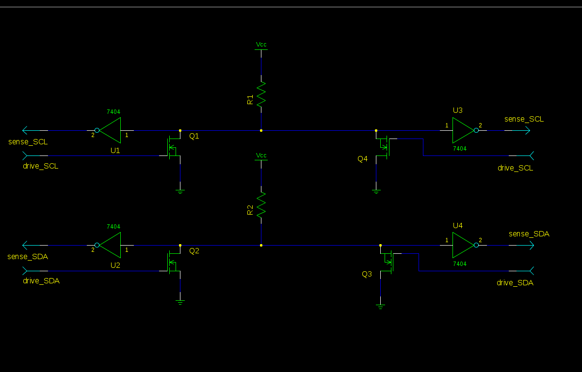
The above diagram is a basic high-level view of the physical layout of an I2C bus. Each side has a FET (Q1-4) that can turn on and connect the bus to ground. It also has a buffer of some kind, allowing it to sense the state of the bus. Each line has a resistor to VCC, which pulls the bus high when idle. The speed of the bus is directly related to the size of the resistor.
I2C works on a master/slave configuration. Some of the devices on the bus will be masters, and some will be slaves. While the spec does allow for multiple masters, it's not very common, and most often the bus will be one master with many slaves. In our case, the ESP8266 will be the master.
So how is the communication actually done? Well, I2C is actually very simple. Only a master can start a transaction, so all the slaves have to do is listen. When a master wants to communicate, the first thing it does is send a START condition. This is accomplished by pulling the data line low, followed by the clock line low. It looks like this:
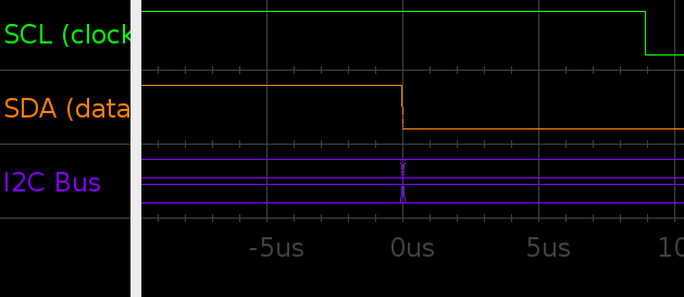
Now the slaves wake up and start listening. After this, the master will send the address of the slave it wants to interact with, followed by any data for that slave or data sent back to the master. When a slave recognises its address on the bus, it sends an ACK by pulling the data line low during an extra clock the master sends, so the master knows it has sent the right address. Once the transaction is complete, the master sends out a STOP condition, which is essentially the reverse of the START condition:
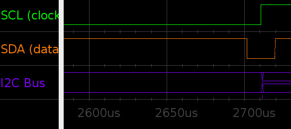
With both lines low, the clock line is pulled high first, followed by the data line. Notice that the master has to first pull the data line low so that both lines are low before issuing the stop. The reason START and STOP commands are distinguishable from data is because the data line should never change while the clock line is high. During normal transmission, the data line only changes when the clock is low. Let's take a quick look at a full transaction:
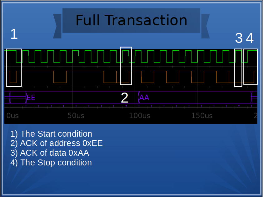
The slave responds to the START condition, sees its address on the bus, gives an ACK, receives the data 0xAA, gives another ACK, and then the master ends the transaction by sending a STOP condition.
The most important things to remember:
- A slave cannot initiate communication, only a master
- A slave must send an ACK during the "9th clock" if the address/data is sees is valid
- The only time the data line can change when the clock is high is during a START or STOP
- Every I2C transaction starts with a START and ends with a STOP