 shlonkin
ATtiny10 resources
UPDATE:
A huge thanks to Keri DuPrey, Nat Blundell and others who have been continually improving the code. The latest version is here:
ATtiny4_5_9_10_20_40Programmer.ino
And a useful GUI by Keri is here:
GUI: ATTiny4_5_9_10_20_40_Programmer.jar
Also, avr-libc 1.7 and newer support ATtiny10! I have not tried it, but I reckon you can now use avr-gcc for the tiny10. However, with only 1kB of program memory, assembly is still useful.
The ATtiny10 is an intriguing little thing. It's the size of a grain of rice and has just 6 little SOT23 pins, but inside lies all the capabilities of an 8-bit AVR microcontroller. Everything from 4 analog input channels to a 16-bit timer with 2 possible pwm outputs to all your basic digital functionality. And at 45 yen a piece, there's little reason not to pick one up to play with. Or two... or ten.
Then once you get home and sit down at your computer, you realize that you are in for a bit more homework than you expected. ICSP doesn't work, common C compilers don't work, hardly anyone online has done DIY stuff with them.
But hark! Do not forsake hope. I am here to aid you on your journey. First, I will guide you to the references that aided me: (The most useful of these was the last one, but it is in Japanese.)
Hardware
Now let's think about hardware. If you are willing to purchase an AVR programmer, go ahead. It's an easy solution that will definitely work. In that case, you can skip down to the assembly examples.
If you would rather do this the hard way(possibly more educational and satisfying), I'll show you how to program the ATtiny10 with only your Arduino, AVR Studio(or anything that will turn your assembly into a hex file) and a few resistors. Also, if you want to make use of all four I/O pins, you will need a 12V power supply for reprogramming.
Here is the basic hardware setup. Thanks to pcm1723 for this drawing and so much more.
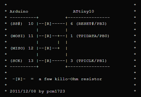
Really, some of those resistors may be unnecessary, but they don't hurt. You can see that it is making use of the usual SPI pins, and indeed we are going to make use of the SPI library to handle the communication details. Anyway, I got tired of setting up wires on a breadboard, so I just made this little pcb with 2.2kohm resistors that plugs right into the Arduino. It also has a connector and jumper for applying 12V to the reset pin. This is only necessary if you disable the reset pin for I/O use.

Note that pin 1 goes in the top right corner. It faces the same direction as the chip on the arduino. Also note that the ATtiny10 needs to be on an adapter to plug into the DIP socket. I would like the option of using the chips without an adapter, so I want to make something that clamps the chip onto a breakout board without solder. I'll post again if I make something like that.
Software
Well, that was simple enough. Now for the software.
First, you will need to generate a hex file for your program. One simple and guaranteed to work method is by using AVR Studio, which is free to download from the Atmel website(here). Set your device to ATtiny10, make a new assembly file project thing, write your code, and click "build solution" in the build menu. Your hex file will be buried in a folder in the AVR Studio projects folder. Look for a folder with your project's name and somewhere inside will be a debug folder. hex is inside of that one.
Then we have to get the program onto the chip.
A big thanks again to pcm1723 for getting me started with the code for the arduino. They posted a simple sketch that uses the TPI interface to read all the memory on the chip and send it via serial to a computer....

 jaromir.sukuba
 PixJuan
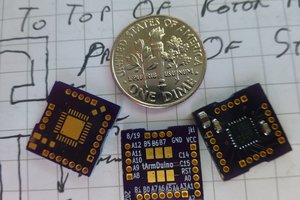
 doctek
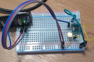
 Simon Merrett
I also suggest this post that shows step by step how to program the ATtiny10 using Platformio or the terminal with a USBASP: http://www.bitbanging.space/attiny10/2020/03/23/programming-attiny10.html