 Chris Miller
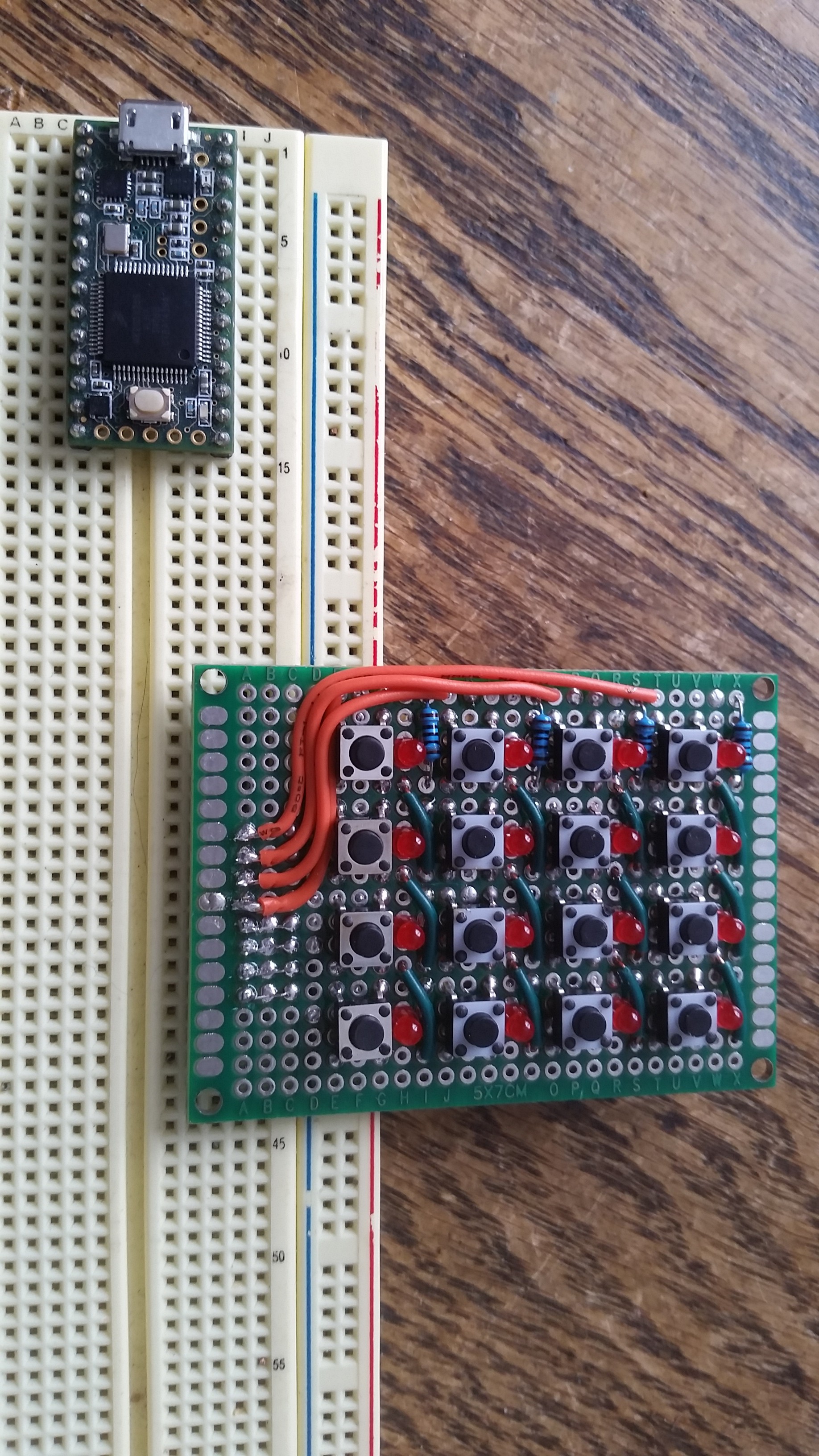
I wanted to create a button pad with at least 16 pushbuttons, and ideally, an LED per button to show status. The easiest way would be a Teensy pin for each button and LED, but that would be at least 32 gpios. The Teensy 3.2 I had on hand didn't have anywhere near that many available unless I soldered wires on the bottom. So I thought it would be a fun challenge to build a multiplexed board that uses on 8 gpios. The rows and columns each get a pin. The columns are connected through a single diode with it's cathode connected to the Teensy. The rows of LEDs are also diodes, so altering the direction of current flow will either light the LED at the row/col junction, or test the switch.
The code to read such a multiplexed beast was somewhat tricky at first, but came easy once I proved the concept. The grid is scanned in a nested loop around 1000 times per second. First all 8 gpios are set to input mode to ensure all LEDs are off and no current is flowing. The LEDs are then scanned, by row, then by column. If the current LED should be on, the corresponding row is set to output mode, HIGH and the column is set to output mode LOW. onIf it's supposed to be off, no pins change. Each led has 48us to stay on, and is then turned off by resetting it's row/col to inputs. At 1000 iterations per second, this give the illusion of the LEDs being on solid.

Then, a few times per second, the rows and columns are iterated again, but this time the rows are set to input, LOW. The columns are set to input with a pullup. Then the column is read with digitalRead(). If the value is high we're reading the pullup signal and the button is not pressed. If the value is low, the switch is pressed and the input is connected to the LOW output on the row.
Button press timestamps are stored in a 2 dimensional array so that software debouncing can be performed. If a button is pressed and the last press was less than say, 100ms ago, we ignore that press.
I found that when switching from LED mode to button reading mode, I needed to pause for one ms before performing the read. I assume that there was some charge built up in the rows and columns, and that needed to discharge before I could reliably read the inputs.
Discussions
Become a Hackaday.io Member
Create an account to leave a comment. Already have an account? Log In.