 Paul DeCarlo
Background:
Desired state configuration is a popular concept that is often used when provisioning servers for the first time and to enforce compliance in running systems. We extend this concept to circuitry using services that are designed for resilience and healthy operation in areas where network connectivity may be intermittent. This approach allows us to change the behavior of a connected circuitry at run-time and allow for interesting scenarios involving hardware redundancy.
The Azure IoT Edge runtime from Microsoft allows us to form a solid basis for the project. This runtime runs as a service on local hardware and allows for orchestration of containerized "modules" which are configured per device in the Azure cloud. Two system modules are always employed, the edge-agent which obtains and applies module deployment configurations and the edge-hub which allows for cached messaging to the cloud and inter-module communication.
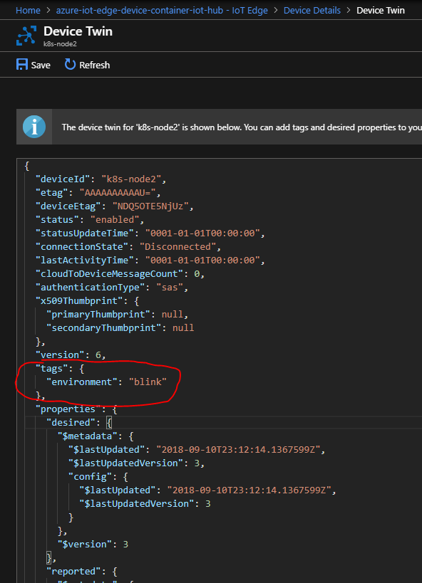
We started off by creating an Azure IoT Edge module using the Azure IoT NodeJS SDK. This module receives a twin configuration which specifies desired and reported properties for a given device. We employ a Domain Specific Language which is parsed into a Johny 5 configuration. This allows us to define how a circuit should functionin the cloud, and apply it to our IoT Edge module.
An example configuration is provided below:
"config": "{\"peripherals\":[{\"type\":\"Led\",\"name\":\"alarm\",\"settings\":{\"pin\":\"GPIO18\"},\"initialState\": {\"method\":\"blink\",\"period\":500},\"outputAlias\":\"alias2\"},{\"type\":\"Button\",\"name\":\"button\",\"settings\":{\"pin\":\"GPIO20\"},\"outputAlias\":\"alias1\"}]}",
This example defines an LED device on GPIO18 with an initalState of blinking on/off every 500ms. The state of the LED is able to propagate to other modules using the outputAlias. A button is also employed on GPIO20 which publishes state changes to alias1. In such a configuration, we can independently respond to state changes in additional modules by routing the outputAlias.
We currently support configuration of a thermometer, LED, and Button device using this mechanism.
Steps to reproduce:
To begin, you will need a Microsoft Azure subscription with a deployed IoT Hub. You can deploy an IoT Hub to an existing subscription by following this guide.
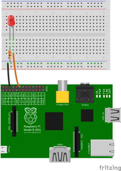
Next, we you will want to begin configuration of your hardware by connecting an LED to GPIO18 of the Raspberry Pi. Instructions for this process can be found here.
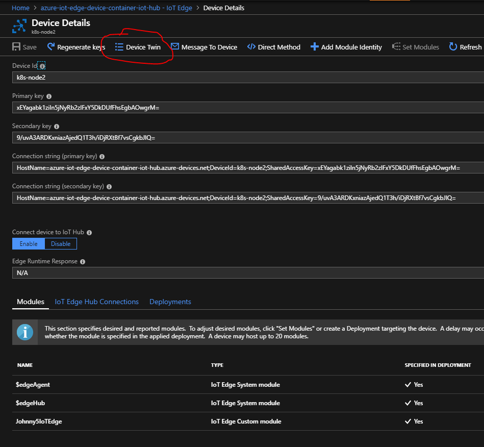
With circuitry and cloud services prepared, you will want to install the Azure IoT Edge runtime to your Raspberry Pi by following this guide. Once the runtime is installed, you will need to manually provision the device by following these instructions.
Next we will create a special deployment within Azure that will allow us to blink our LED.
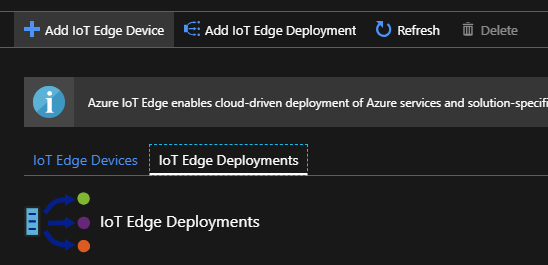
Create a deployment as shown below:
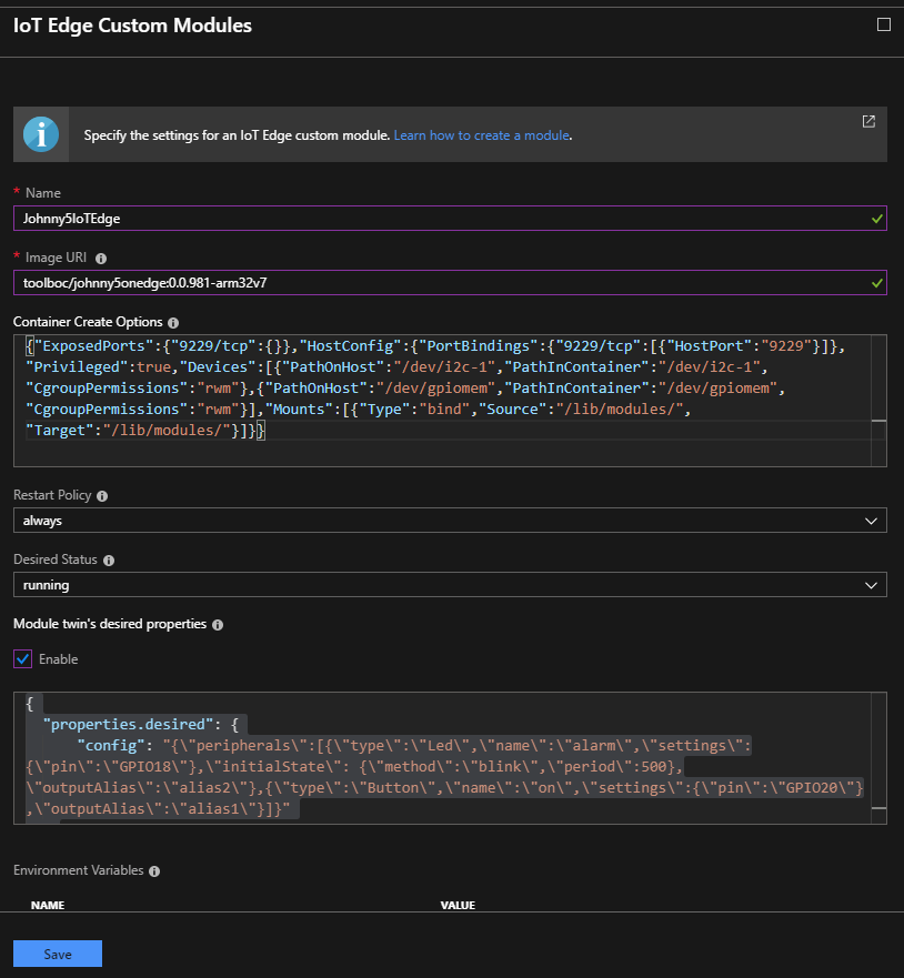
The image URI:
toolboc/johnny5onedge:0.0.981-arm32v7
The container create options:
{"ExposedPorts":{"9229/tcp":{}},"HostConfig":{"PortBindings":{"9229/tcp":[{"HostPort":"9229"}]},"Privileged":true,"Devices":[{"PathOnHost":"/dev/i2c-1","PathInContainer":"/dev/i2c-1","CgroupPermissions":"rwm"},{"PathOnHost":"/dev/gpiomem","PathInContainer":"/dev/gpiomem","CgroupPermissions":"rwm"}],"Mounts":[{"Type":"bind","Source":"/lib/modules/","Target":"/lib/modules/"}]}}
The Module twin's desired properties:
{
  "properties.desired": {
      "config": "{\"peripherals\":[{\"type\":\"Led\",\"name\":\"alarm\",\"settings\":{\"pin\":\"GPIO18\"},\"initialState\": {\"method\":\"blink\",\"period\":500},\"outputAlias\":\"alias2\"},{\"type\":\"Button\",\"name\":\"on\",\"settings\":{\"pin\":\"GPIO20\"},\"outputAlias\":\"alias1\"}]}"
  }
}
Save when you are finished. Then skip through the "Specify Routes" and "Specify Metrics" sections until you get to...
Read more »

 Andrew Byrley
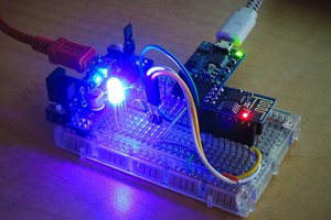
 Blecky
 Emilio P.G. Ficara
 Florian Wilhelm Dirnberger