 John Adams
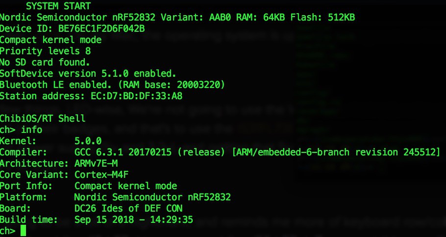
We're about ten days into our work now and I've spent most of them installing KiCad, figuring out our hardware needs, and getting my development environment up and running. Since we're now on cortex-m4 (last years KW01 was cortex-m0) we can still use the gcc-arm tool chain and Makefiles from our previous ChibiOs build. This means same OS as last year, and full support for things like uGFX. On my Mac, the operating system is up and running and we have full serial access to the board
Look at that boot!
On the hardware front, we have some decisions, and some issues.
Bill reports that:
wpaul [1:47 AM]
"The nRF52840 supports up to 32MHz SPI clock!!!"
Yeah, right: but only for one bus!  (SPIM3)
Oh, and by the way, that one bus?
It's totally broken in the early engineering versions of the silicon.
So that preview board you bought? Yeah, it won't work with that.
Seriously, what the hell.
The nRF52832 had three SPIM blocks. The nRF52840 has 4. Only the 4th supports a clock speed faster than 8MHz.
The instances can be configfured for SPIM or I2C, and they're tied to the same interrupt pin, but nothing about that necessarily restricts the speed of the SPIM logic. So now, not only can I not achieve the simultaneous display and SD card speed that I wanted, I have to order another DK board because the preview board I have is basically worthless to me.
So, what this means is that 1) We need to immediately order new development boards. 2) Our current boards are useless. 3) We can't do any SW development until this happens.
#badgelife. Sigh.
In other areas we've made some decisions. Audio will be over I2S. Most likely using the CS4344. If everything works out, we're going to get DMA audio, stereo, and 24bit/96Khz output which makes the audio nerd in me very, very happy. I will do everything I can this year to reduce noise -- last year we had to stop PCB changes and go to production before I could fix noise issues on the board.
LED-wise, We're not going to use the WS2182's. Instead, we're going to do something similar to what Queercon did on their badges, and that's to use the IS31FL736 chip to control our LEDs. This means that we're going to have to have a dual power supply (5v and 3.3v), and getting that 5v is going to require some sort of buck converter to get from our LiPo's 3.7V to 5.5V.
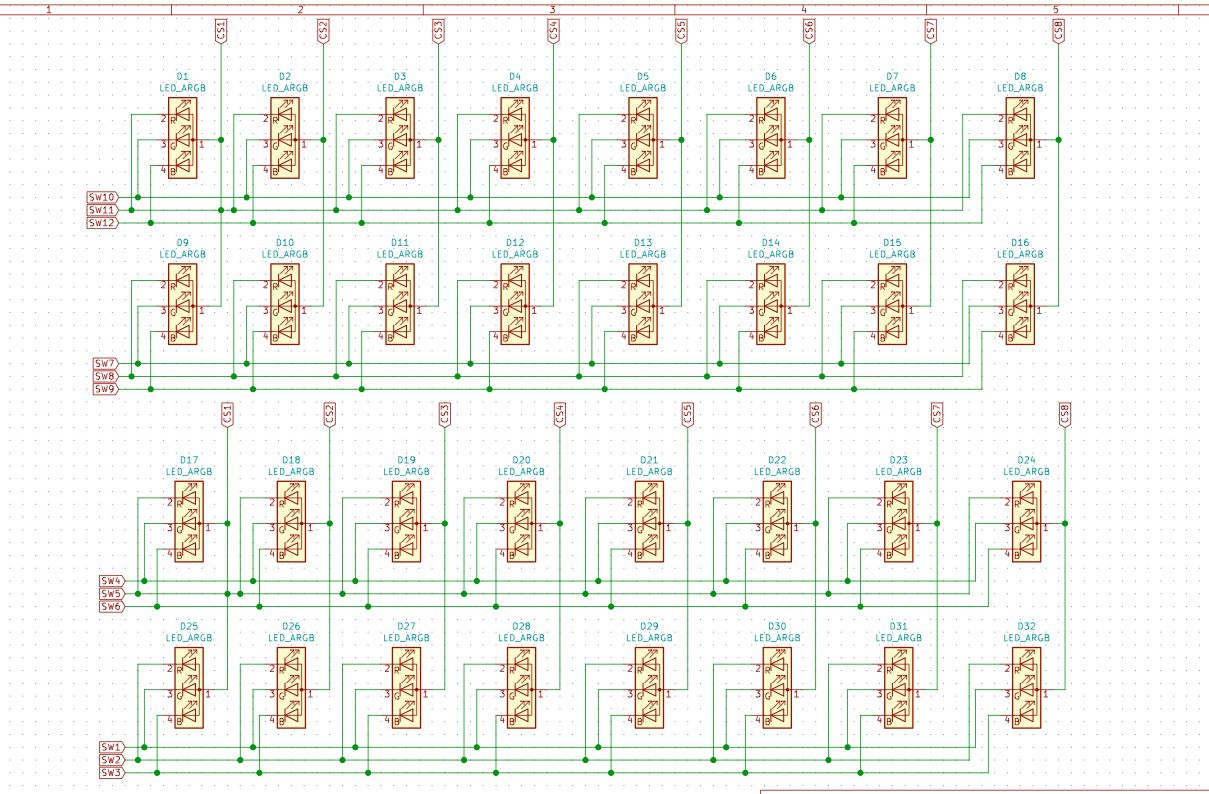
The LED wiring is going to be a bit of a nightmare, and reminds me more of keyboard row/column wiring than anything else. we're also going from less bling (12 LEDs) to way more bling (32 LEDs). To support this we will most likely be using slightly large LiPos and a stronger charging circuit this year. I am also very interested in adding the MAX17043 to the board to have a full "fuel gauge" circuit to read battery life. We didn't have one last year and it was annoying.
I've also decided that we're going to remove a lot of the debugging LEDs from the board. There may be spots on the board for them, but I'm probably going to mark them DNP to reduce costs. We'll see what the cost differences are.
So many wires...
That's it for now, see you next week.
Discussions
Become a Hackaday.io Member
Create an account to leave a comment. Already have an account? Log In.