 Stephen Harrison
Before:
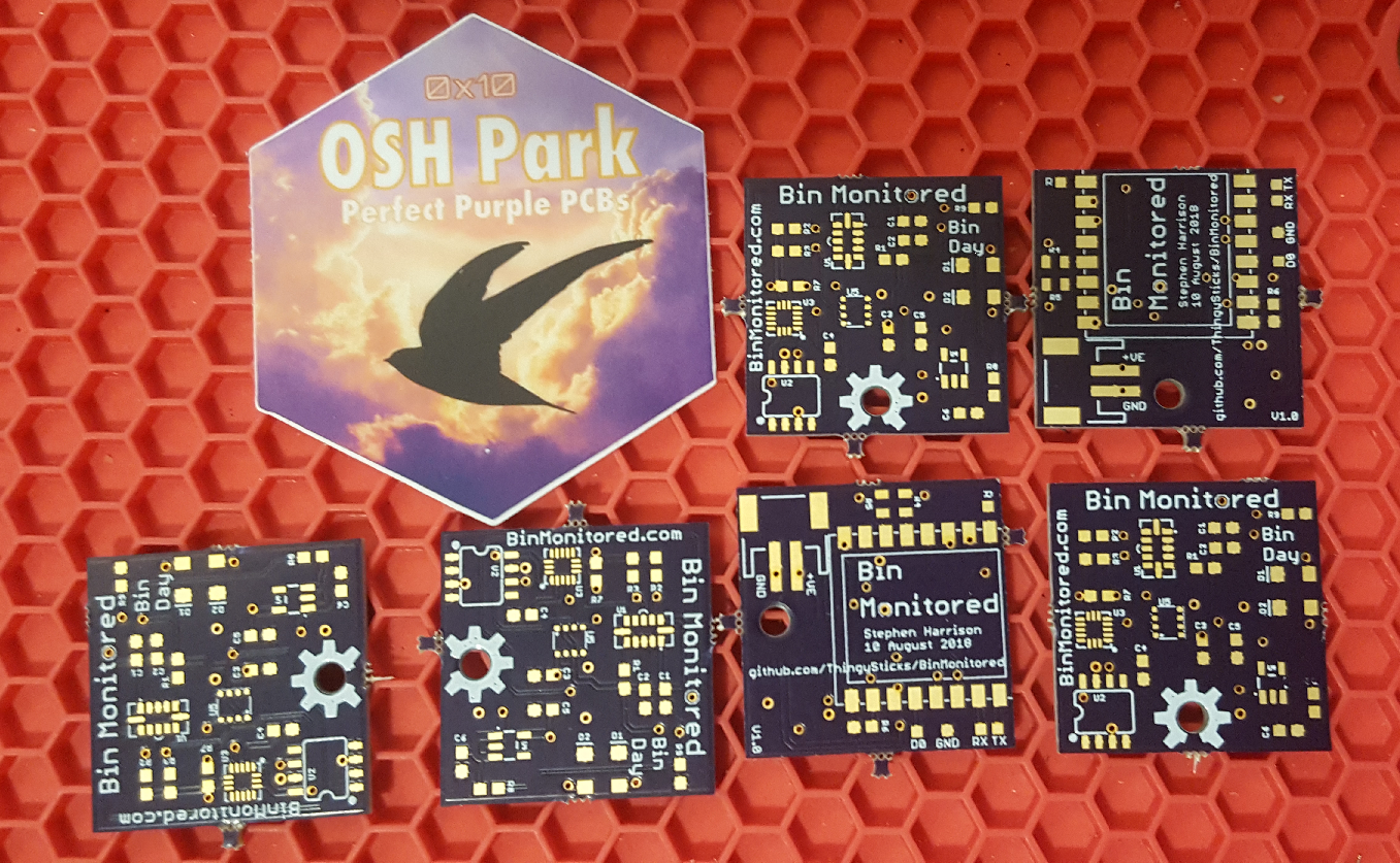
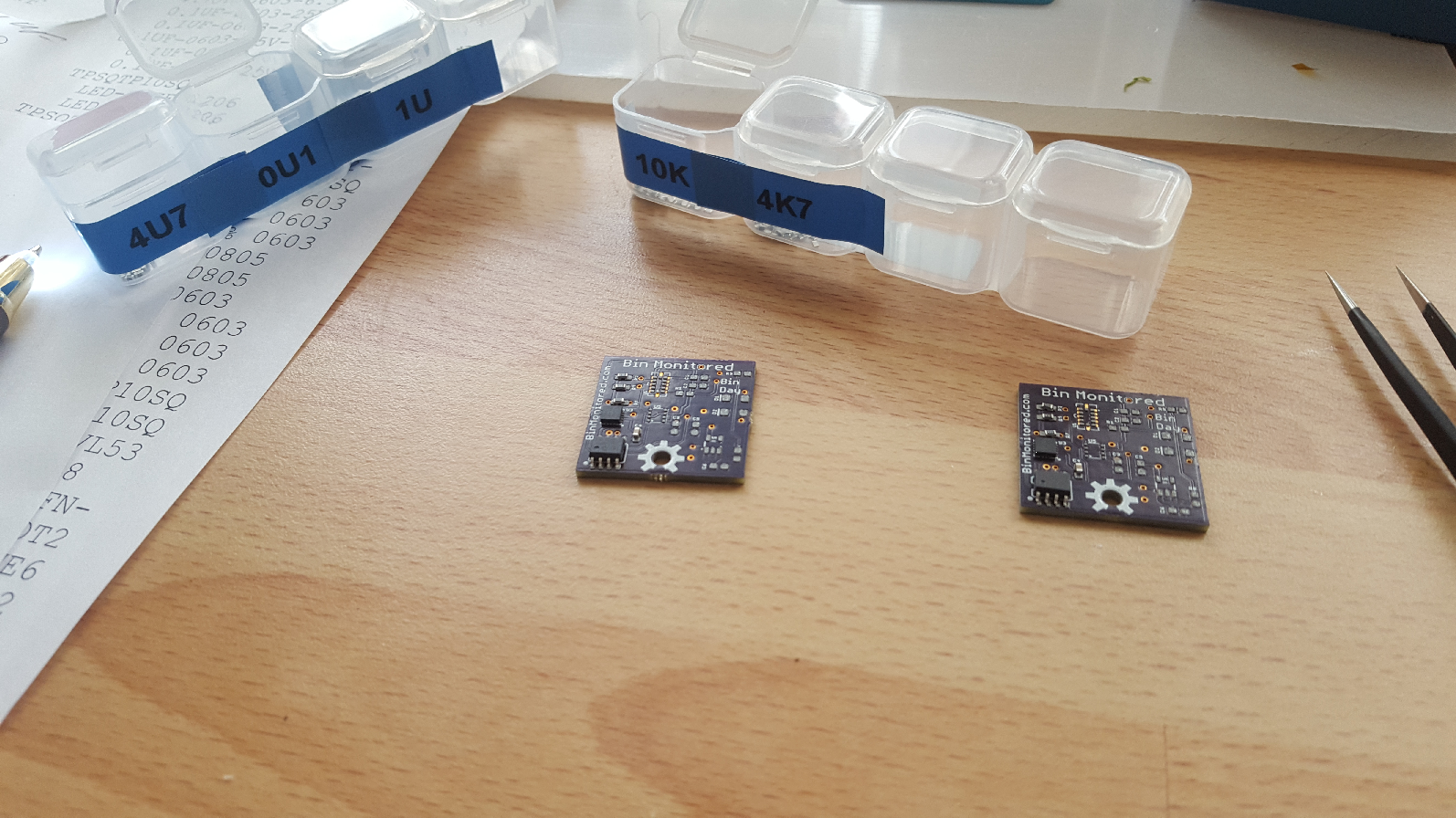
After (I only made up 2 boards initially):
I'd like to say PCB assembly went easily and the PCB worked first time, it almost did, except shortly after I started reflowing the first PCB I noticed I had the distance sensor the wrong way around so I immediately put that PCB to one side. However the second PCB came out a treat and did work first time :-)
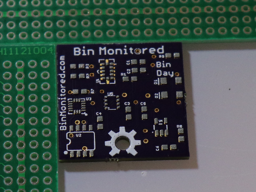
As you can tell from the very purple colouring of the PCBs (and the sticker!) I got the PCBs from OSHPark, I had a stencil made for the top layer at OSHStencils. Each PCB is 25.4mm x 25.4mm (it's almost as if I'd designed them to fit within the Hackaday Square Inch Contest....).
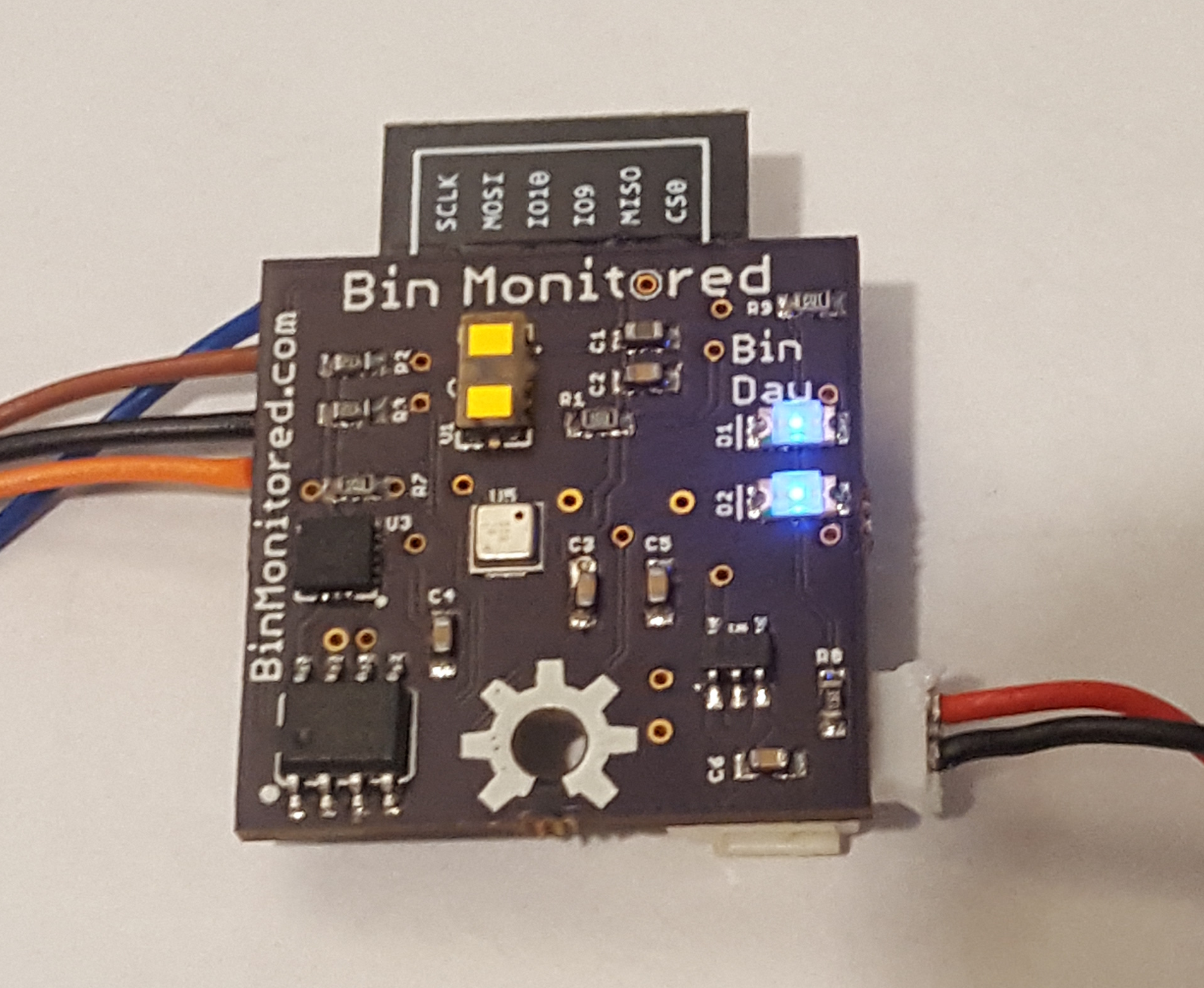
The accelerometer, distance sensor and environment sensor are not at all hand solderable so this was always going to be a job for a stencil and reflow. Theirs only a few easy components on the bottom layer so I hand soldered that.
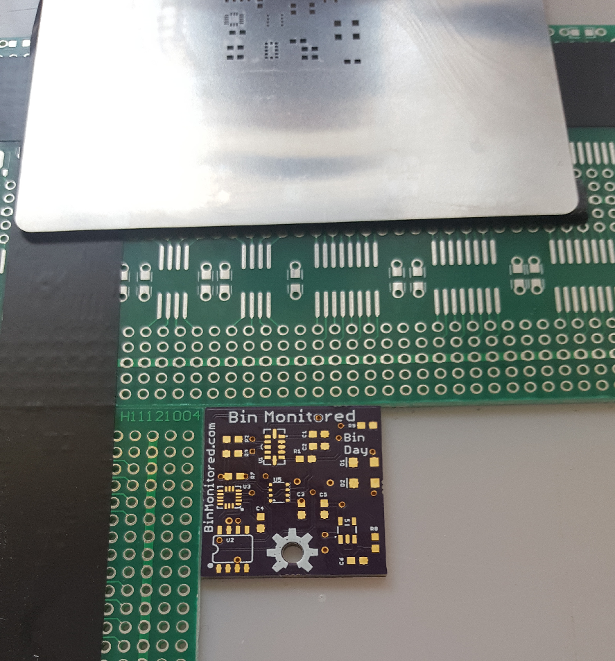
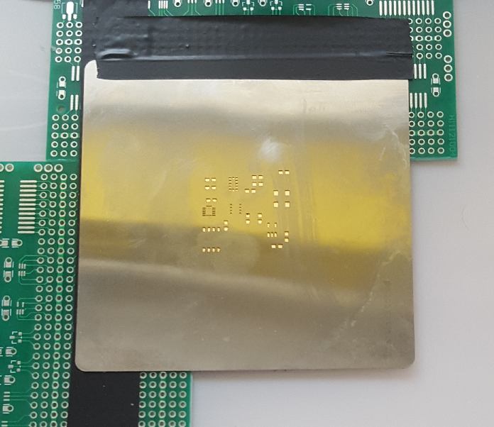
I carefully aligned the PCB with the stencil and applied solder paste.
And used the Steve-Pick-And-Place-Machine to populate the PCB (i.e. me and a pair of tweezers) .
Then I used my ReflowR to reflow the PCB...
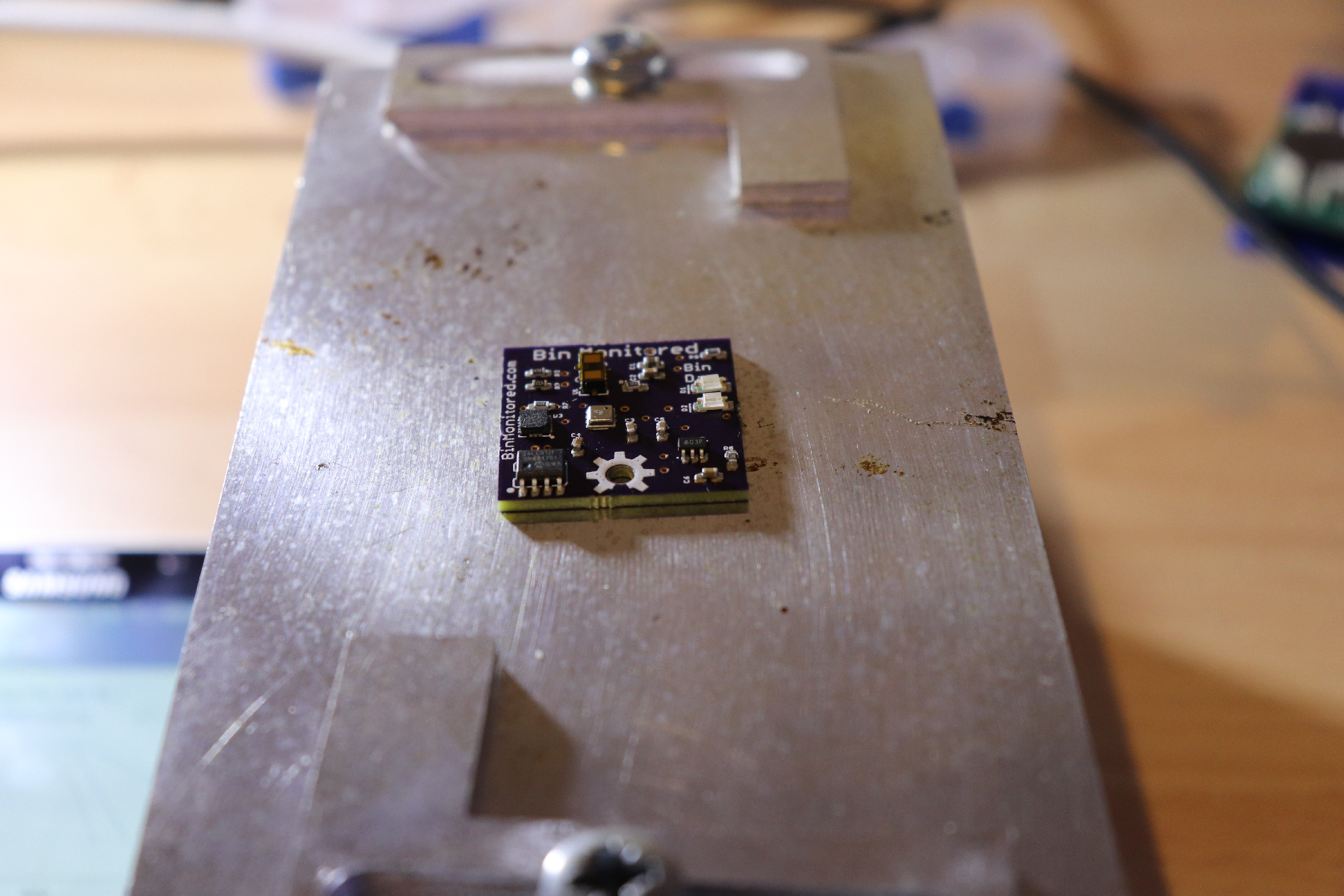
The nice thing about the ReflowR is you can set it to hot and then remove / rework components if needed. Some time later I did this to the first PCB that I had the distance sensor the wrong way around on. Sadly shortly after that my ReflowR stopped working.
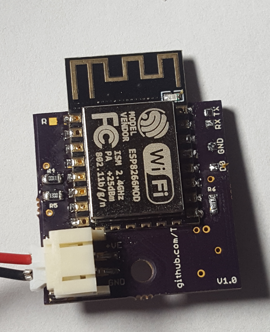
Populating the bottom layer of the PCB is much easier and I did this by hand soldering. The JST socket is probably a little overkill but it was handy during development and testing, however for a final product the battery holder is probably just as well soldered to the PCB. Notice also the solder pads for TX, RX, D0 and GND used to program the ESP 8266.
Discussions
Become a Hackaday.io Member
Create an account to leave a comment. Already have an account? Log In.