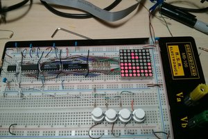
Powering the Display Unit
The LED panel has a max power consumption of 700W/m2 and an average of 300W/m2. After doing all the calculations, the current requirement for a single panel comes out roughly to be 1.92Amps - 3.84Amps. A 5V-10A SMPS was already available with us so we have used it in this project. Although power supply with 4Amps of current can also be used.
How the HUB Works?
- Pinout
- A,B,C,D
are part of the row decoder circuitry. They are used to select which two rows of the Matrix are enabled. Here D is the most significant bit and A is the least significant bit. - Pins R0,G0,B0 are used to provide color data to the upper half of the matrix. i.e. the rows from 0 to 15. Similarly, Pins R1,G1,B1 are used to provide color data to the lower half of the matrix. i.e. the rows from 16 to 32.
- CLK - Clock to the panel is applied at this pin.
- OE - Output Enable. Writing a logic HIGH on this pin would turn ON the display on the panel. A logic LOW on this pin would turn OFF the display.
- STB - Strobe. Also called LATCH, A logic HIGH on this pin puts the data held by the 32bit shift register to the 32bit output register. If at this point the OE pin is made HIGH, the data in the 32bit output register will be displayed on the two rows selected by DCBA inputs.
- Row Selection
The 32x32 LED panel is divided into halves.
1) Upper Half containing rows 0-15
2) Lower Half containing rows 16-32
The De-multiplexer Inputs DCBA selects one row from each of the two halves as per the table below:
| D | C | B | A | Row selected in Upper Half | Row Selected in Lower Half |
|---|---|---|---|---|---|
| 0 | 0 | 0 | 0 | 0 | 16 |
| 0 | 0 | 0 | 1 | 1 | 17 |
| 0 | 0 | 1 | 0 | 2 | 18 |
| 0 | 0 | 1 | 1 | 3 | 19 |
| 0 | 1 | 0 | 0 | 4 | 20 |
| 0 | 1 | 0 | 1 | 5 | 21 |
| 0 | 1 | 1 | 0 | 6 | 22 |
| 0 | 1 | 1 | 1 | 7 | 23 |
| 1 | 0 | 0 | 0 | 8 | 24 |
| 1 | 0 | 0 | 1 | 9 | 25 |
| 1 | 0 | 1 | 0 | 10 | 26 |
| 1 | 0 | 1 | 1 | 11 | 27 |
| 1 | 1 | 0 | 0 | 12 | 28 |
| 1 | 1 | 0 | 1 | 13 | 29 |
| 1 | 1 | 1 | 0 | 14 | 30 |
| 1 | 1 | 1 | 1 | 15 | 31 |
The code snippet below performs the row selection operation
void selectRow(int address_in_decimal) //address decoder function
{
 switch(address_in_decimal)
  {
   case 0: //row 0 and 16 are selected
   {
    FIO0CLR |= 0xF0000000; //DCBA = 0000
    FIO0SET |= 0x00000000; //DCBA = XXXX
    break;
   }
   //case 1 to 14 have been omitted from here to save space
   //check the attached files to view complete code
   case 15: //row 15 and 31 are selected
    {
     FIO0CLR |= 0x00000000; //DCBA = XXXX
     FIO0SET |= 0xF0000000; //DCBA = 1111
     break;
    }
   //The FIO0CLR is written to clear the previous data
   // because we are oring the data.
   default:
    {
     break;
    }
  }
}
The matrix has 1024(32x32) RGB LED's in total. All of the 1024 LED's can't be driven at once as they would require us to have large number of connections as well as the current required to drive all at once will be huge.
So the efficient way to display information is to turn the LED's off and on multiple times at high frequency to create an illusion of a static display
We found a frequency of 3MHZ to be enough for a single display. However, as the the number of displays in cascade are increased the frequency has to be increased. The LPC2148 is capable of delivering frequencies of up-to 60MHZ.
Displaying data on desired pixel
- If we try to turn on a particular pixel say the 31st column on the 0th row we have to send '0' on the first clock '1' on the second clock and then '0's on the subsequent clocks.
- But while doing this we will see the '1' shifting with each clock. To avoid this we will keep the OE disabled and turn it enable it only on the 31st clock while keeping the STB enable during the whole time.
- Doing this will make it seem as if the desired pixel is turning ON directly but actually the has been shifted with the clock to the desired location.
- Repeating the above process at high frequency for desired pixels will make it seem as if desired SHAPES are lighting up at desired locations.
The data to be displayed on Panel is stored in a 32-by-32 array of type _Bool (named MAIN MATRIX) in our program. Each bit in the array represents the state...
 Kevin Cuzner
 PointyOintment
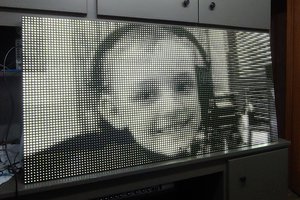
 George Gardner
 Bharbour