The LED panel has a max power consumption of 700W/m2 and an average of 300W/m2. After doing all the calculations, the current requirement for a single panel comes out roughly to be 1.92Amps - 3.84Amps. A 5V-10A SMPS was already available with us so we have used it in this project. Although power supply with 4Amps of current can also be used.
How the HUB Works?
Pinout
A,B,C,D are part of the row decoder circuitry. They are used to select which two rows of the Matrix are enabled. Here D is the most significant bit and A is the least significant bit.
Pins R0,G0,B0 are used to provide color data to the upper half of the matrix. i.e. the rows from 0 to 15. Similarly, Pins R1,G1,B1 are used to provide color data to the lower half of the matrix. i.e. the rows from 16 to 32.
CLK - Clock to the panel is applied at this pin.
OE - Output Enable. Writing a logic HIGH on this pin would turn ON the display on the panel. A logic LOW on this pin would turn OFF the display.
STB - Strobe. Also called LATCH, A logic HIGH on this pin puts the data held by the 32bit shift register to the 32bit output register. If at this point the OE pin is made HIGH, the data in the 32bit output register will be displayed on the two rows selected by DCBA inputs.
Row Selection
The 32x32 LED panel is divided into halves.
1) Upper Half containing rows 0-15
2) Lower Half containing rows 16-32
The De-multiplexer Inputs DCBA selects one row from each of the two halves as per the table below:
D
C
B
A
Row selected in Upper Half
Row Selected in Lower Half
0
0
0
0
0
16
0
0
0
1
1
17
0
0
1
0
2
18
0
0
1
1
3
19
0
1
0
0
4
20
0
1
0
1
5
21
0
1
1
0
6
22
0
1
1
1
7
23
1
0
0
0
8
24
1
0
0
1
9
25
1
0
1
0
10
26
1
0
1
1
11
27
1
1
0
0
12
28
1
1
0
1
13
29
1
1
1
0
14
30
1
1
1
1
15
31
The code snippet below performs the row selection operation
voidselectRow(int address_in_decimal) //address decoder function{
switch(address_in_decimal)
{
case0: //row 0 and 16 are selected
{
FIO0CLR |= 0xF0000000; //DCBA = 0000
FIO0SET |= 0x00000000; //DCBA = XXXX break;
}
//case 1 to 14 have been omitted from here to save space//check the attached files to view complete codecase15: //row 15 and 31 are selected
{
FIO0CLR |= 0x00000000; //DCBA = XXXX
FIO0SET |= 0xF0000000; //DCBA = 1111break;
}
//The FIO0CLR is written to clear the previous data
// because we are oring the data.
default:
{
break;
}
}
}
The matrix has 1024(32x32) RGB LED's in total. All of the 1024 LED's can't be driven at once as they would require us to have large number of connections as well as the current required to drive all at once will be huge.
So the efficient way to display information is to turn the LED's off and on multiple times at high frequency to create an illusion of a static display
We found a frequency of 3MHZ to be enough for a single display. However, as the the number of displays in cascade are increased the frequency has to be increased. The LPC2148 is capable of delivering frequencies of up-to 60MHZ.
Displaying data on desired pixel
If we try to turn on a particular pixel say the 31st column on the 0th row we have to send '0' on the first clock '1' on the second clock and then '0's on the subsequent clocks.
But while doing this we will see the '1' shifting with each clock. To avoid this we will keep the OE disabled and turn it enable it only on the 31st clock while keeping the STB enable during the whole time.
Doing this will make it seem as if the desired pixel is turning ON directly but actually the has been shifted with the clock to the desired location.
Repeating the above process at high frequency for desired pixels will make it seem as if desired SHAPES are lighting up at desired locations.
The data to be displayed on Panel is stored in a 32-by-32 array of type _Bool (named MAIN MATRIX) in our program. Each bit in the array represents the state of the LED at that position in the display matrix. i.e bit "0" is LED OFF and bit "1" is LED ON. The data is scanned row by row. A function named putshapetomainmatrix() is used to display the data in the main matrix on to the LED board
Row 0 and 16 are first selected.
Data of the (0th row, 0th column) and (16th row, 0th column) are taken together and fed to the panel's R0,G0,B0 Pins (with feedRGB0 function) and R1,G1,B1 pins (with feedRGB1 function) respectively. A clock pulse is then given to shift the data by one bit to the left.
Now the same process is followed till the data of (0th row, 31st column) and (16th row, 31st column) is fed. This would take 32 clocks in total.
Once a row has been fed we make STROBE (or LATCH) and OE pin HIGH. This displays the data that we have taken from the 32-by-32 array (i.e. row 0 and row 16) on the panel's 0th and 16th rows.
Now row 1 and 17 are selected and the same process is repeated till we have displayed data for row 15 and row 31.
If we want to cascade N number of displays the the array size will increase to 32-by-n and the number of clocks required for the operations would increase to n.
The code snippet below performs the above functionality.
The above code is used to only feed one type of color, in our complete code we have used a separate matrix to overlay the information for 7 possible color combinations.
GAME LOGIC
Running the TETRIS game requires the following functions to be implemented:
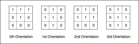
Generate different shapes namely L,T,Z,Square,Line. The shapes L,T will have 4 possible orientations. Z and Line will have two possible orientations and Square will have only one orientation because it looks the same after each 90 degree rotation. For generating this we have created 5 3D arrays and have overlayed them on the MAIN MATRIX.
Moving the shapes LEFT and RIGHT. This is done by decreasing/ increasing the column index with ever press of the left button or right button.
Collision detection: The shapes should stop once they encounter any ON LED to their left, right or bottom.
As shown above the shape T has four orientations and each shape is a 3x3 matrix. Consider the 2nd orientation, if any ON led is detected on the 3rd row 1st column or 3rd row 2nd column or the 3rd row 3rd column, we will say that a down collision has been detected and the row index will stop incrementing. So,this function will require us to know the current row index, current column index , current shape type and the current shape orientation. This function has been implemented as down_collision_detection(). The same logic has been used to implement left_collision_detection(),right_collision_detection(),rotate_collision_detection().
Score updater: Every time a down collision is detected a function checkrowforones() scans all the rows starting from the 31st row till the 10th row ( because after this the game stops ) and checks if any row is filled with '1's, if yes then then the data above is shifted down to the particular row creating an illusion that the row has been cleared a separate variable score is incremented.
Game over: Whenever any of the columns get filled till the 10th row the game is over. to detect this, every time a down collision is detected we check if the current row index is 10 if yes then the game is over if not the row index continues to increment to shift the shapes down. After the game is over a new matrix named _Bool gameover is diplayed in the LED board. The matrix is 32x32 and already contains 'GAME' 'OVER' and 'SCORE' written plus some space at the bottom of the score numerals.
Score display: A separate matrix named _Bool scoreDisplay is used which has the data corresponding to the numerals 0 to 9 and this function uses the score variable to update the corresponding score in the mainmatrix.