0%
0%
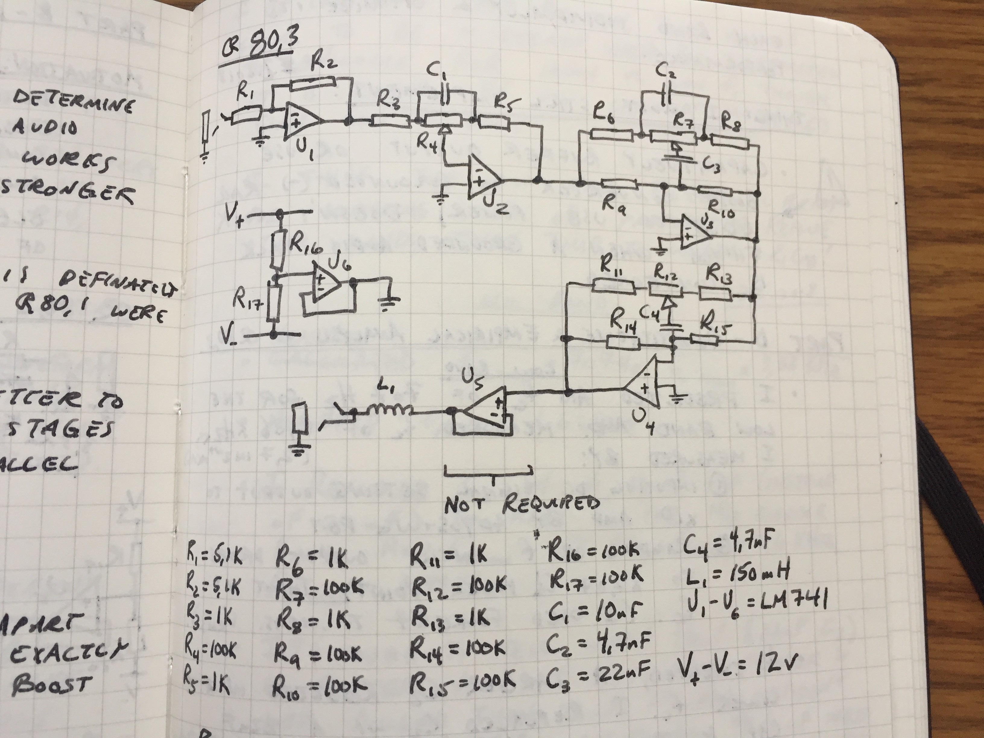
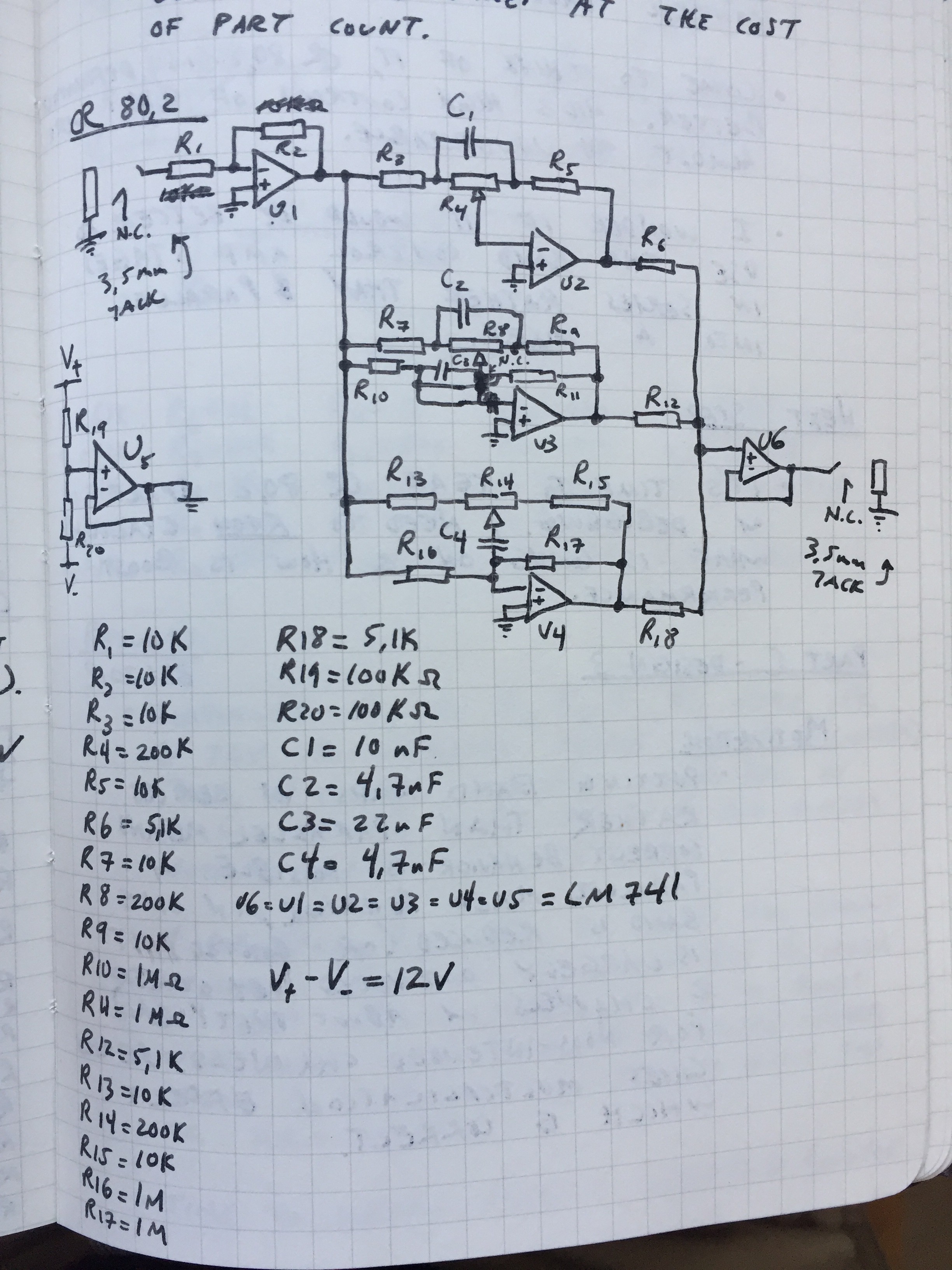
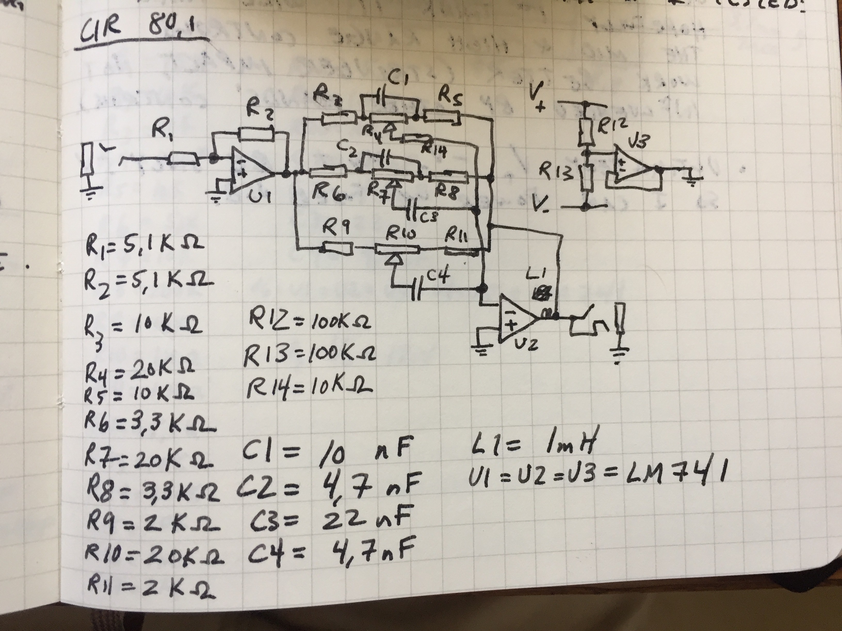
Graphic Equalizer
A 3-band audio equalizer!
 Grant Giesbrecht
Become a Hackaday.io member
Already have an account? Log in.
Just one more thing
To make the experience fit your profile, pick a username and tell us what interests you.
Pick an awesome username
hackaday.io/
Your profile's URL: hackaday.io/username. Max 25 alphanumeric characters.
Pick a few interests
Projects that share your interests
People that share your interests
 j
j
 agp.cooper
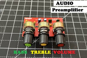
 Sagar 001
 Andrea Console
Nice build. What I miss is a volume control. A front plate can be easy made from PCB material. For example: https://www.bonedo.de/fileadmin/_processed_/a/f/csm_Bastl_Kastl_v15_66a62558ad.jpg