0%
0%
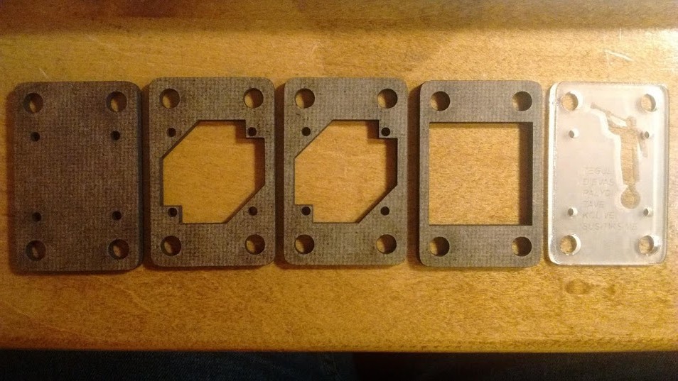
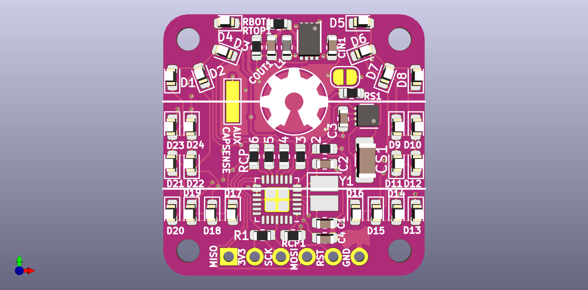
Peppermint
A flag-themed blinky countdown memento for time spent apart, with capacitive touch switch.
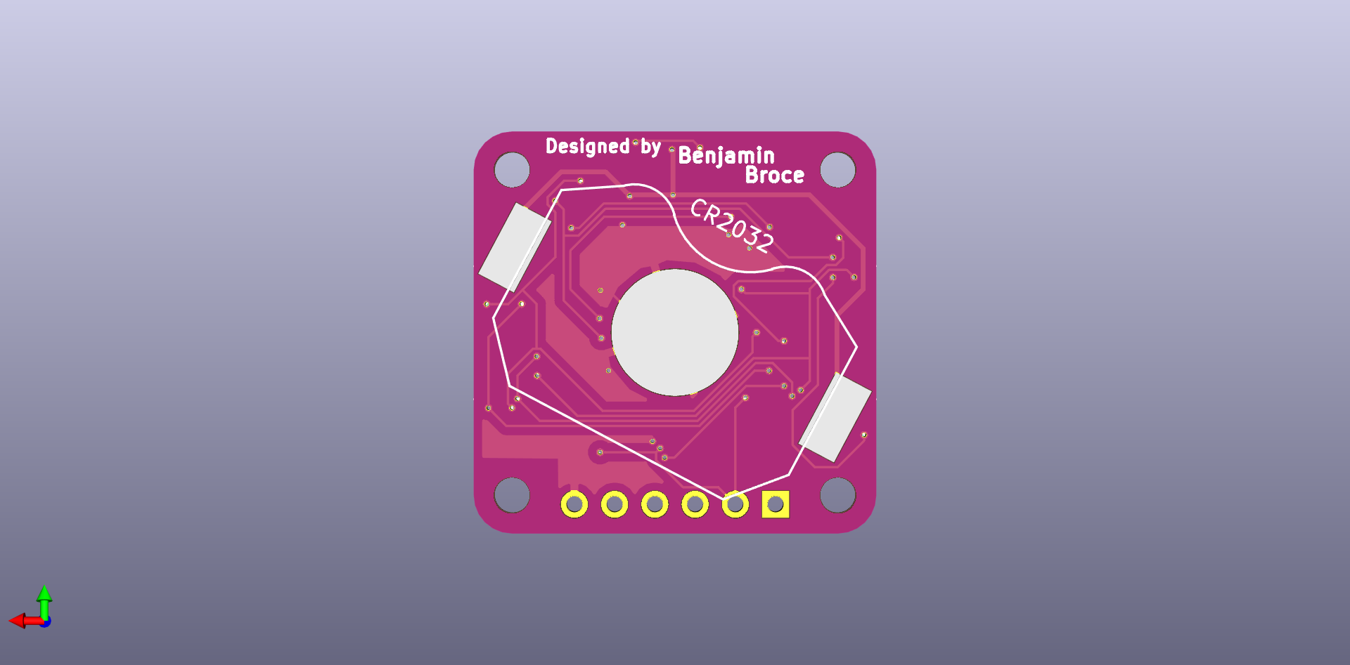
 Benjamin Broce
Become a Hackaday.io member
Already have an account? Log in.
Just one more thing
To make the experience fit your profile, pick a username and tell us what interests you.
Pick an awesome username
hackaday.io/
Your profile's URL: hackaday.io/username. Max 25 alphanumeric characters.
Pick a few interests
Projects that share your interests
People that share your interests
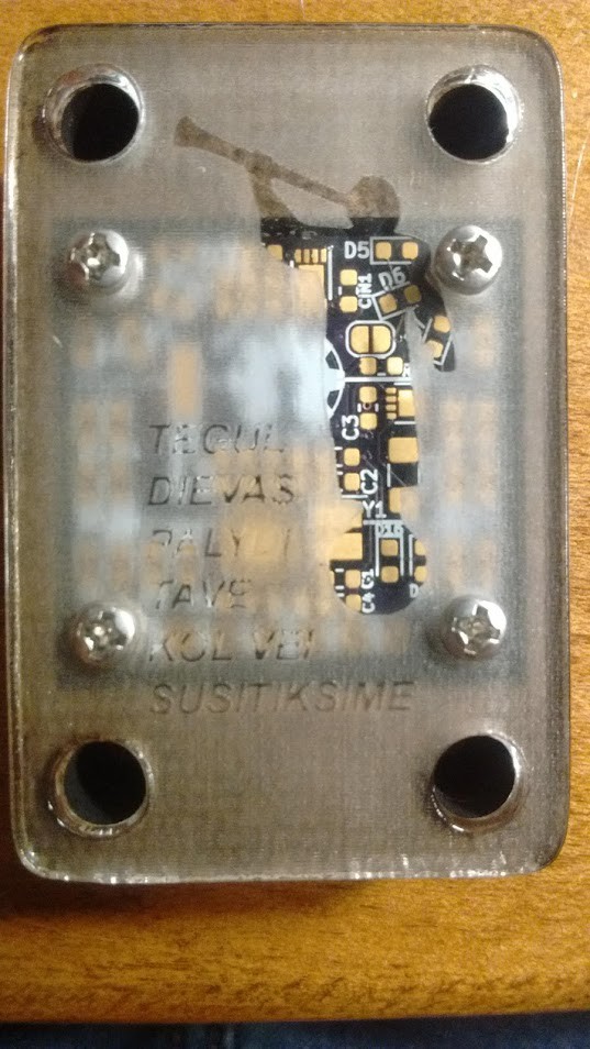
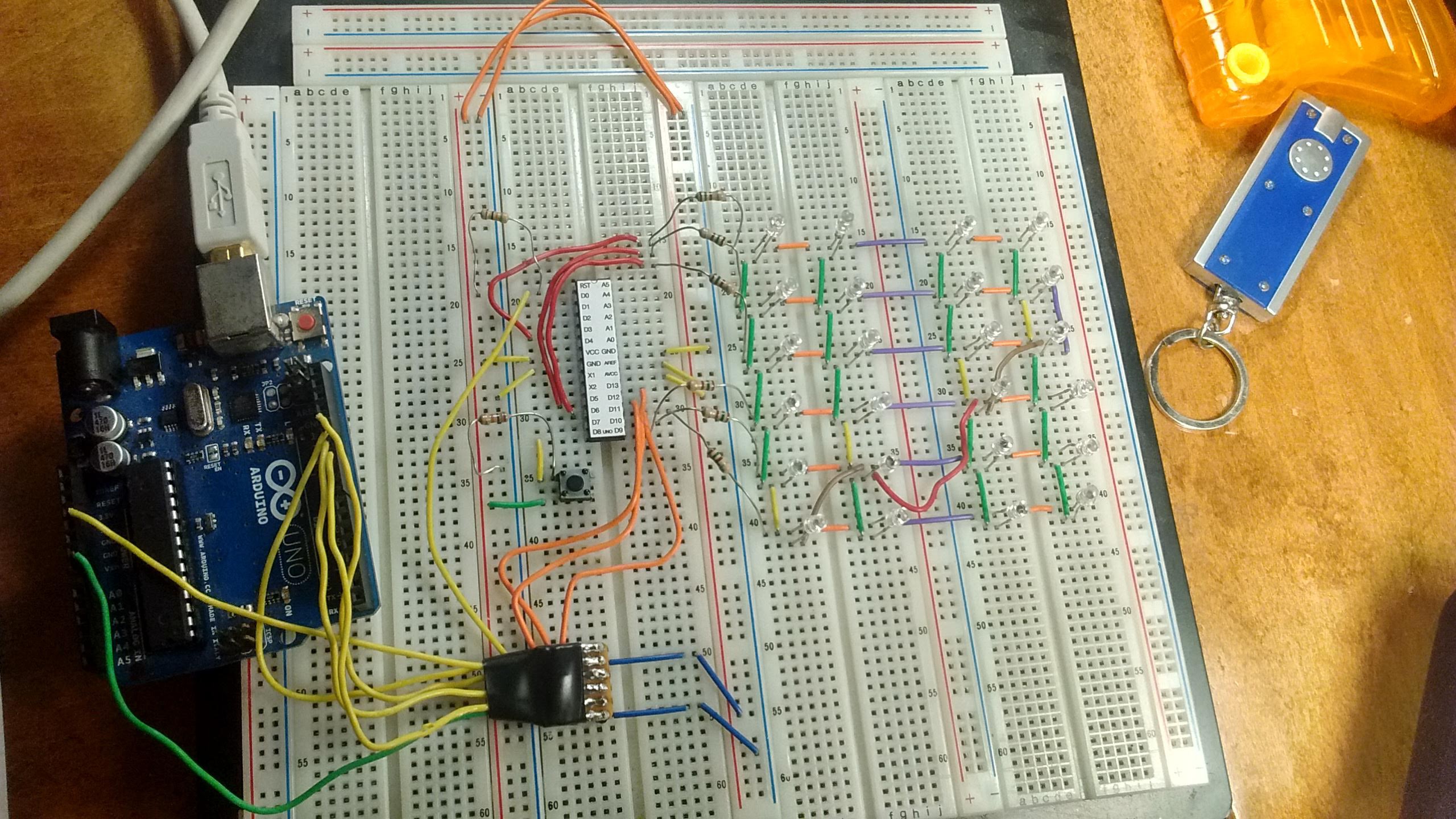
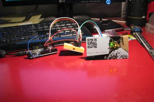
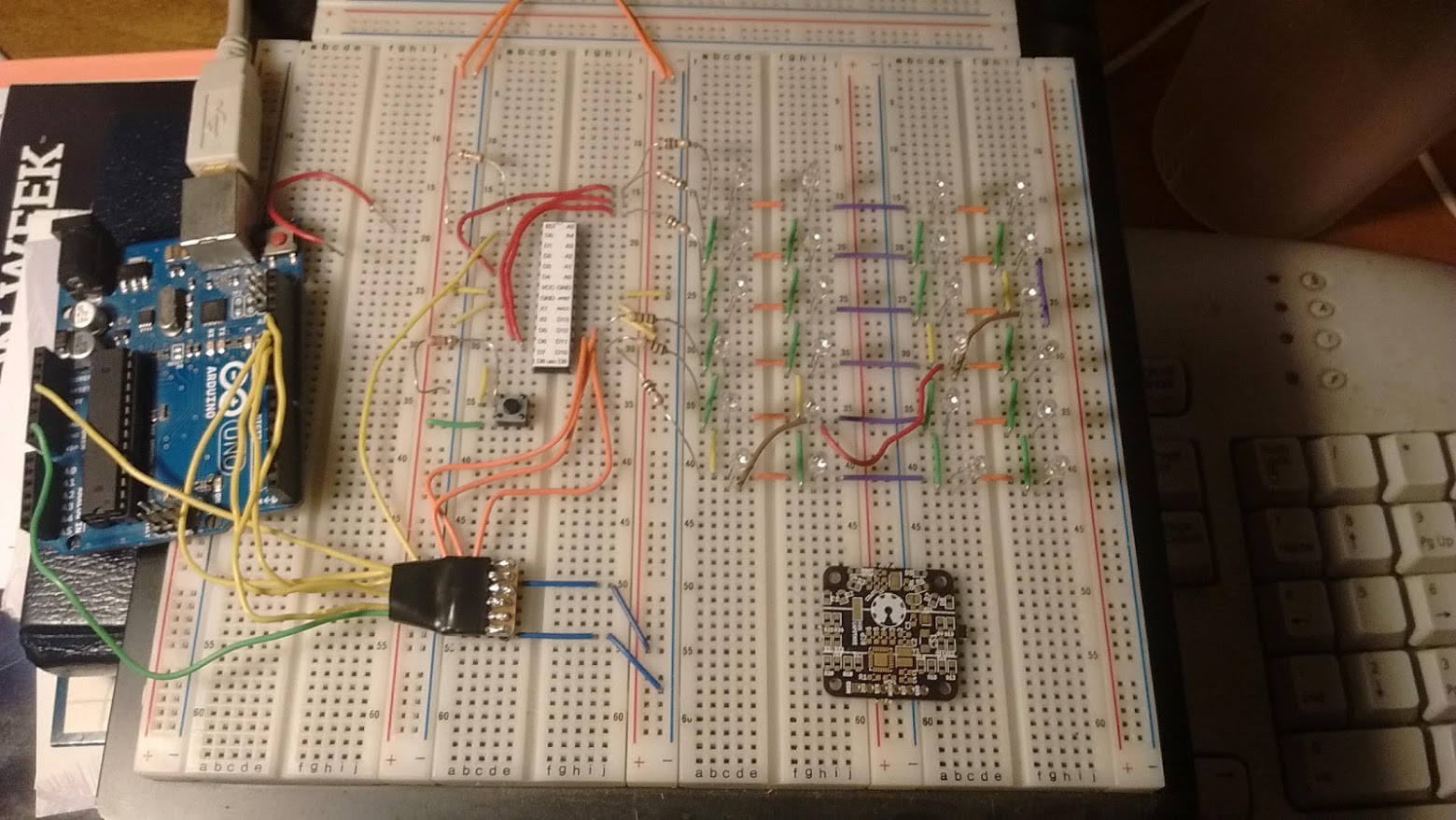 PCB dwarved by it's prototype :)
 uri.shani
 Gee Bartlett
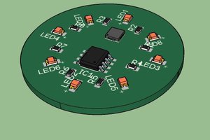
 Luc
Luc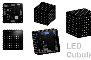
 Jack Flynn