 Thomas
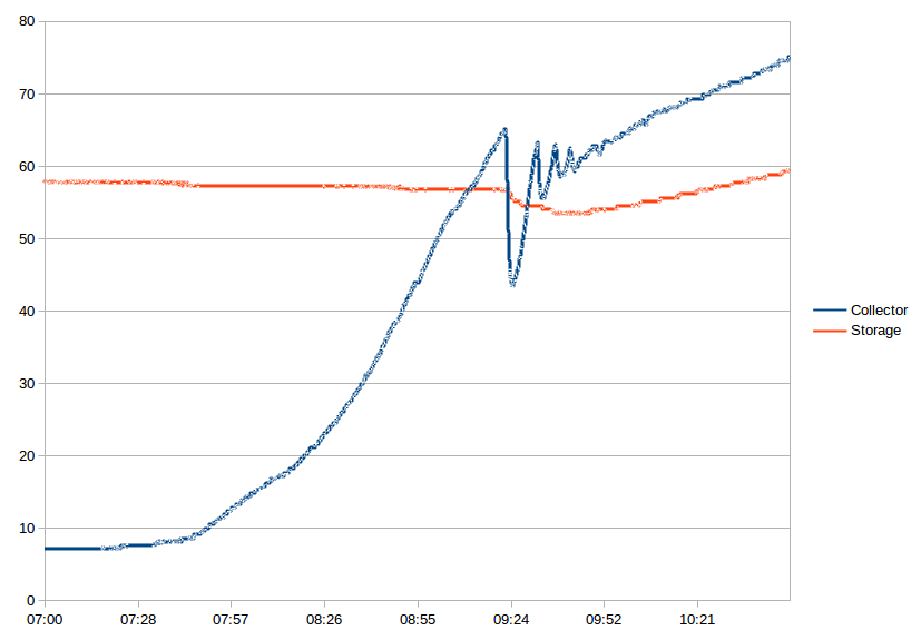
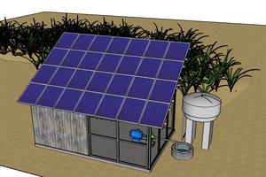
An unexpected cold shower made it clear that I need a new controller for our solar warm water heating system ("split architecture" which is typical for installation in middle and northern Europe - thanks @Saabman for helping me understand that I had no idea how solar heating works in other parts of the world).
Of course this is a prime opportunity for applying the notorious STM8 eForth!

Our house is in Germany, in winter a (fossil fuel) heater is required for heating the top of the storage. The controller responsible for that is independent of the solar heating control, and it starts heating when the temperature at the top of the storage is below a certain threshold (typically in the morning on a sunny February day). An advantage of connectivity is that the weather forecast information can be used to change that behavior. A fail safe design is required but the usage of NTC sensors should make that easier. A second sensor for the storage will be required as a overheating protection: a failing storage sensor can lead to 400l of boiling water!
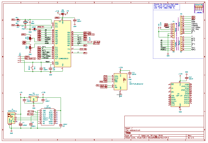
The old controller used a PIC16C84 and the code was borrowed from Microchip AN512 (plus LPF, serial interface etc). The temperature sensors I used then were KTY10 (2K type), the field-and-garden-variety sensors those days, and they're still good.
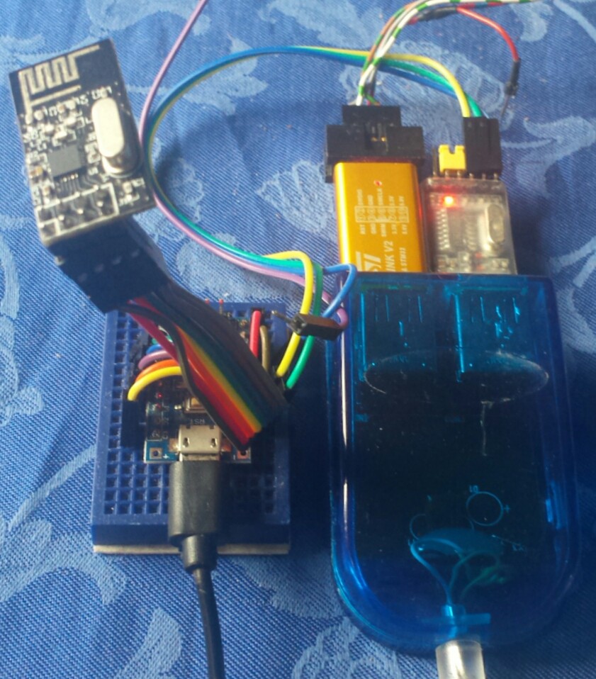
For a quick fix I reused the 5V power supply and the SSR pump control from the old PIC based solution. For now I use a $0.80 STM8S103F3P6 "Mindev" breakout board on a small "solderless breadboard" and some patch wires.The solar collector and hot water storage have a KTY10 sensor each. Both sensors are in a voltage divider with a 2000R 1% "reference resistor" :
 (3.3V)
   |
 2000R
   |
   *------*---(PC4)
   |      |
 KTY10  KTY10
  COL    STO
   |      |
 (PA1)  (PA2)
The collector sensor is selected by PA1, the storage sensor (middle sensor in the picture) by PA2. A 3rd sensor, storage top, will be selected by PB4.
The first hack "solar.fs" had the following features:
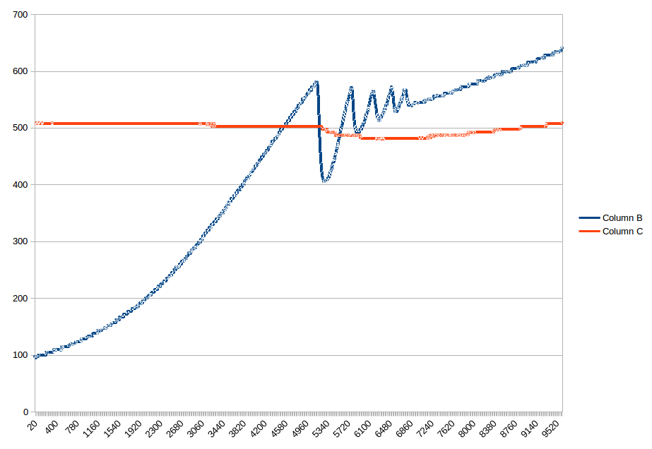
- linearisation and low pass filer for both sensors
- robust measurement in a background task
- safety limit for the storage temperature
- 820 bytes code size (> 2500 bytes free!)
The second hack "solar-nrf24.fs" uses the STM8-nRF24L01 library to add some basic connectivity.
My prototype solar controller and the receiver are connected to an 8-pin nRF24L01+ module (more likely a clone) as follows:
| Pin nRF24L01 | Signal nRF24L01 | STM8S103F3 |
|---|---|---|
| 1 | (Gnd) | (Gnd) |
| 2 | (VCC) | (3.3V) |
| 3 | CE | PD2 |
| 4 | /CSN | PD3 |
| 5 | SCK | PC5 |
| 6 | MOSI | PC6 |
| 7 | MISO | PC7 |
| 8 | IRQ | PC3 |
For connectivity I see two cheap standard options:
- ESP8266 (e.g. ESP-01) connected to the serial interface
- nRF24L01+ connectivity developed here
I plan to design a PCB that offers both options


 iarakistain
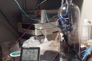
 Darren Blaxcell, aka Pork
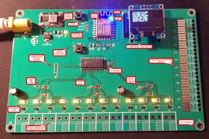
 Red Tuka
 Frank Vigilante
Split systems are very common here in Australia as well mainly because people don’t like the look of the tank on the roof. I have a issue of the water freezing in the water supply to the tank.
The close coupled system I have uses glass tubes like a vacuum insulated flask in which the water is heated from the sun. The glass tubes attach directly to the tank. Most sunny days even through winter the water will boil ( temperatures between -6 and +10degC )
The booster I was referring to is a heater element to “boost” the water Temperature on cloudy days.
I was particularly interested in your data because I use a heat exchange on a slow combustion wood heater to heat the water on cloudy days but I have noticed if the fire is not hot enough I loose more water temperature due to water cooling in the pipes between the tank and the fire. Which is a similar issue you have noted when your pump first starts of a morning. My system currently relies on a thermosiphon between the fire and the tank but I have been considering adding a pump to have better control over the flow and minimize the heat loss.