 Jasper Sikken
This device is special because the hardware and software is open source, it is Arduino compatible, and it is a cheap tool all hardware designers should have. It works up to 19.8V, 5A and 16W/21W depending wether you choose the smaller or larger heat sink. The load can be set to constant current, constant power, or constant resistance by simply typing it into the Arduino serial monitor. The constant current circuit is implemented in hardware using an opamp, a mosfet, and a current sense resistor. The input for that circuit is made with a 12 bit DAC. The constant power and constant resistance mode is implemented in software. Load voltage and current are measured using a pair of high precision opamps (MCP6072) and the microcontrollers 12 bit ADC. Battery capacity can be measured by loading the battery with constant current and it will simply display the mAh's in the Arduino Serial Monitor. To protect the battery against undervoltage the load is removed when the voltage falls below a configurable threshold. The device can also be used to simply log a voltage or current over time.
Dave Jones from EEvblog discussed my previous revision device in everyone's favorite segment Mailbag. Check it out.
Specifications
- Current set/read range: 0 to 5 A
- Current set/read resolution: 12-bit, 1.22 mA/bit
- Current set/read accuracy : 5% in range 0.1 to 5A
- Current settle time (10-90%): rise 20us, fall 8us typical
- Pulsed current: minimum 156us wide pulse, or 2.9kHz square wave (0 and 5A)
- Voltage read range : 0 to 19.8V
- Voltage read resolution: 12-bit, 4.83 mV/bit
- Voltage read accuracy: 5% in the range 0.15 to 19.8V
- Max power with standard 16W heat sink at 25 degrees Celsius
- Max power with extra large 21W heat sink at 25 degrees Celsius
- MOSFET: BTS133. It has ESD, thermal, overvoltage, overcurrent, and overload protection!
- Microcontroller: STM32F103C8T6 ARM Cortex-M3 (blue pill)
- Power supply: micro USB cable (not included)
- Load connector: 2 pins screw terminal 5.08mm pitch 24-12 AWG, and 4 mm PCB holes for banana plugs
- Net Weight: 80 grams
- Size: 72x54x49mm standard heat sink, 72x54x67mm extra large heat sink
- USB cable is not included

Quick start
- Connect your power source to the plus and minus terminal of electronic load
- Connect USB cable to the computer
- Start Arduino IDE
- Select the COM port (both NL & CR)
- Open Arduino Serial Monitor
- Type any of the commands below
- Every second the voltage, current, power, and capacity are printed to the serial port
Serial Monitor Commands
- Type CC 100 to set a constant current of 100 mA
- Type CP 100 to set a constant power of 100 mW
- Type CR 100 to set a constant resistance of 100 Ohm
- Type pulse 500 5000 500 50 500 2500 500 50 to set repeating pulsed load of 500us@5000mA, 500us@50mA, 500us@2500mA, and 500us@50mA
- Type limit v 1000 to set the undervoltage limit to 1000mV
- Type limit p 15000 to set the power limit to 15W
- Type help for more commands
Storing the data
Arduino Serial Monitor cannot save the serial port data. Well, you can copy what was printed to the screen and store it as a CSV or text file. But I recommend using Realterm because it can store the data in a file and add a timestamp for further processing in other tools, for example in a spreadsheet.
Testing a power supply
Constant voltage power supplies can be tested by applying different loads and see how the voltage is reduced. It may also be used to test a dc-dc converter efficiency under different loads. For example, type cc 100 in the serial monitor and you will see the current being set and the voltage updating at regular interval.
Youtube video with demo of setting the current using R2
And another video where I test a $1.26 1A USB travel adapter
Testing a solar panel
Solar panels generate most power at a certain voltage, the maximum power voltage, Vmp. The Vmp can be found in the IV-curve of a solar panel, which is the current versus the voltage. You can manually apply different loads but the solar radiation may change during testing. To avoid these variations one could make embedded code that quickly tests the solar panel in a second or so.
Testing a thermal electric generator
TEGs generate most power at a certain current, the maximum power current, Imp. The Imp can be found in the IV-curve of a TEG, which is the current versus the voltage. This device is ideal for finding the Imp.
Testing batteries
Battery capacity is usually indicated in mAh (milliamp hours) which is the load current in mA multiplied by the time in hours. This electronic load is ideally suited for battery testing. It can test a battery under constant current, constant power and constant resistance, exactly the three ways capacity is indicated in the battery's datasheet. But be careful. The battery voltage must not drop too low otherwise the battery gets damaged permanently. You first need to type the limit voltage "limit v 1000" (it stops at 1000 mV), "reset" to reset the mAh counter and then "cc 1000" to start the measurement under a load of 1000mA.
Youtube video with demo of measuring battery capacity
Testing a supercapacitor
The capacitance of a supercapacitor can be verified using the electronic load. You need to charge it to let's say 2.0V, then load it with 1A constant current and simply count the seconds for the voltage to drop 1V. The time in seconds is the capacitance in Farad.
This youtube video shows how to test super capacitor capacitance
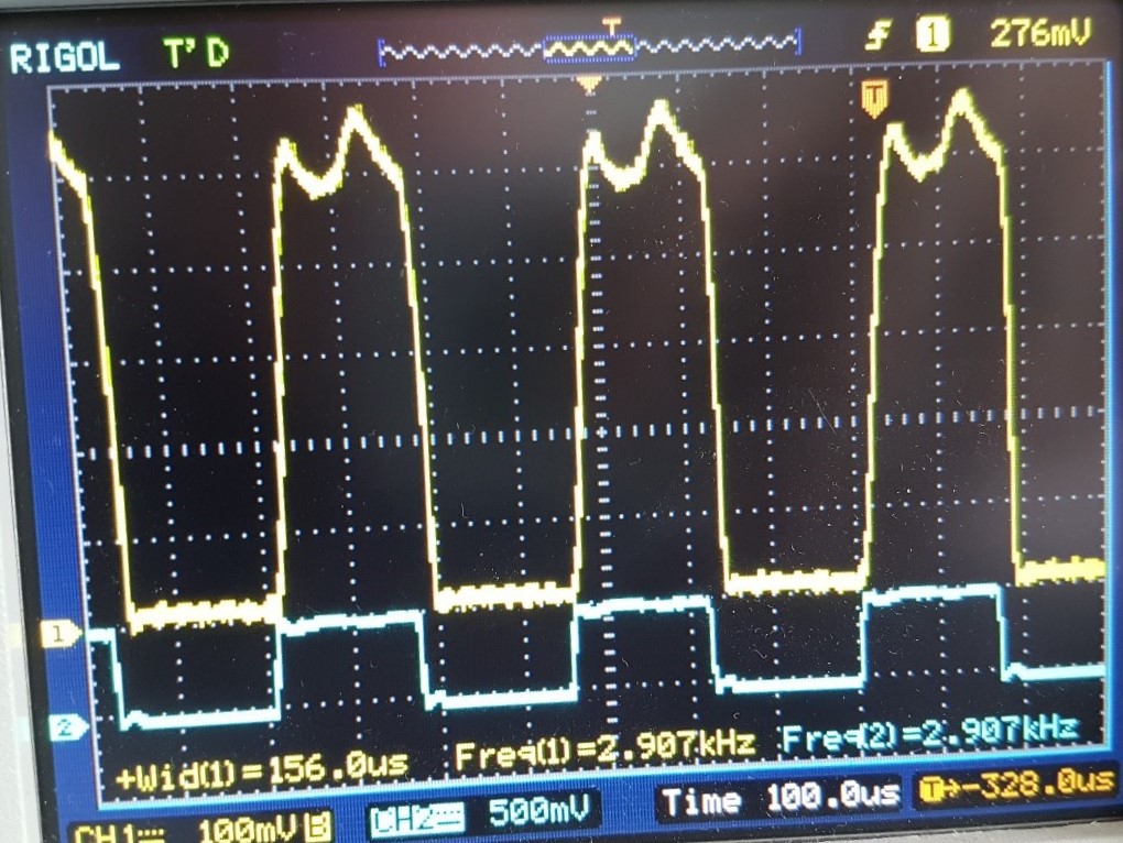
Pulsed load
The constant current circuit settles in just 20us, that is so fast it can be used for pulsed loads. For example GSM module current pulses can be simulated. If you type "pulse 500 5000 500 50 500 2500 500 50" you get a repeating pulsed load of 500us@5000mA, 500us@50mA, 500us@2500mA, and 500us@50mA. And it looks like the picture below.
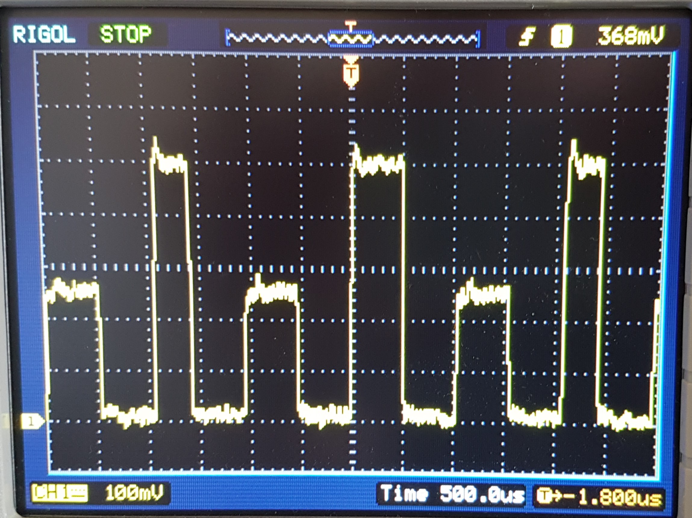
Typing "pulse 0 5000 0 0” basically means 0us at 5000mA, 0us at 0mA. Then the signal looks like this.
As you can see setting duration to 0us actually gives 156us pulse witdh, this is caused by the time it takes to send a new DAC setting from the MCU to the DAC.
Software
The software is open source and published by my brother Bertrik.
Software description here
Actual software is here
Hardware
Hardware is open source and it is published here.
What you get
You will get a fully assembled, pre-programmed, and tested device with the above specifications, it looks like the picture above. The USB cable is not included.
USB driver installation
On a Windows 10 machine (without any drivers or Arduino IDE installed) the device was immediately detected and a serial COM port appeared. On a Windows 7 machine, I had to Download this zip file. Run drivers/win/install_drivers.bat and install_STM_COM_drivers.bat. If that doesn't work I recommend to open Windows device manager, right click on Maple DFU, select update driver, and make Windows search for driver in the folder drivers/win/.
Re-programming the Electronic Load
If you want to update embedded code to the latest version or write your own Arduino program for the STM32 microcontroller, you need to follow the installation steps on this page. It's easiest to program the board over USB because I have already put a bootloader on the STM32 MCU. The embedded code you need to clone or download from this Github page. Once you have installed the STM32 board files you need to select the board "Generic STM32F103C series". If programming fails even though the STM32 shows up as a COM port on your computer you may need to install the USB driver. See USB driver installation above.
Calibration
Using a benchtop power supply and a multimeter you can make your device most accurate at a certain voltage/current.
Calibration the voltage
Let's say you want the voltage reading to be most accurate at around 10V follow these steps
- type "cal r" to reset the old calibration factors, it will reset both the current as the voltage factors
- set your variable power supply to around 10V
- using your multimeter measure the exact voltage on the Electronic Load. Let's say you measure 10.12V.
- type "cal v 10120" in millivolts
- you're done It will store a factor close to 1.000 into flash memory and it will use that from now on to correct the voltage reading.
Calibrating the current
You need to put your multimeter in series with the power supply
Let's say you want the current setting/reading to be most accurate at around 1A follow these steps
- type "cc 1000" to set the current close to 1000 mA,
- read the exact current from your multimeter, let's say 996 mA
- type "cal i 996", current in milliamps.
- You're done It will store two factors close to 1.000 into flash memory and it will use that from now on to correct the current setting and current reading.
To read the calibration factors you need to type "cal". If you want to reset the calibration factors you need to type "cal r".
Thank you for reading all the way to the end.