 Alex Brown
As I’ve got older, I’ve grown to like simplicity. I want to faff around less with the minor details and give myself more time for the fun stuff. This project aimed to remove some faff, although at first it didn’t quite go to plan.
My plan was to make a Honda USB cable, meaning I could connect a 3c or 3mx to a PC without needing two cables and a load of bulk.
DISCLAIMER: This project comes with the usual “thermonuclear war” caveats. It worked for me, it might not work for you. In fact, you could damage your Psion, your USB cable, your computer’s USB port, yourself… Do this at your own risk.
I used:
- 1x USB to RS-232 adapter with a CH340 chip (I used this one)
- 1x Unterminated Honda serial cable (like this)
- Soldering iron
- Scalpel
- Heatshrink (I think I used 1x 1cm diameter and 2x 0.5cm, but I can’t remember)
My initial idea was to buy a 5v TTL adapter from eBay, solder an unterminated Honda cable to the serial pins and, hey presto, a Honda USB cable. This, however, turned out not to be the case. Because Psion RS-232 ports use true RS-232 at +12v and -12v. So, back to the drawing board.
My work on this was on a Saturday a couple of weeks before Christmas. The day hadn’t gone too well - I had struggled with this project, then tried (and failed) to get the Microsoft Macro Assembler running in DOSBox, and finally tried (and failed) to cram as much VHDL into my brain. I’d gone to bed feeling frustrated and disheartened. I woke up the following day still feeling frustrated and disheartened. So I decided to do something about it.
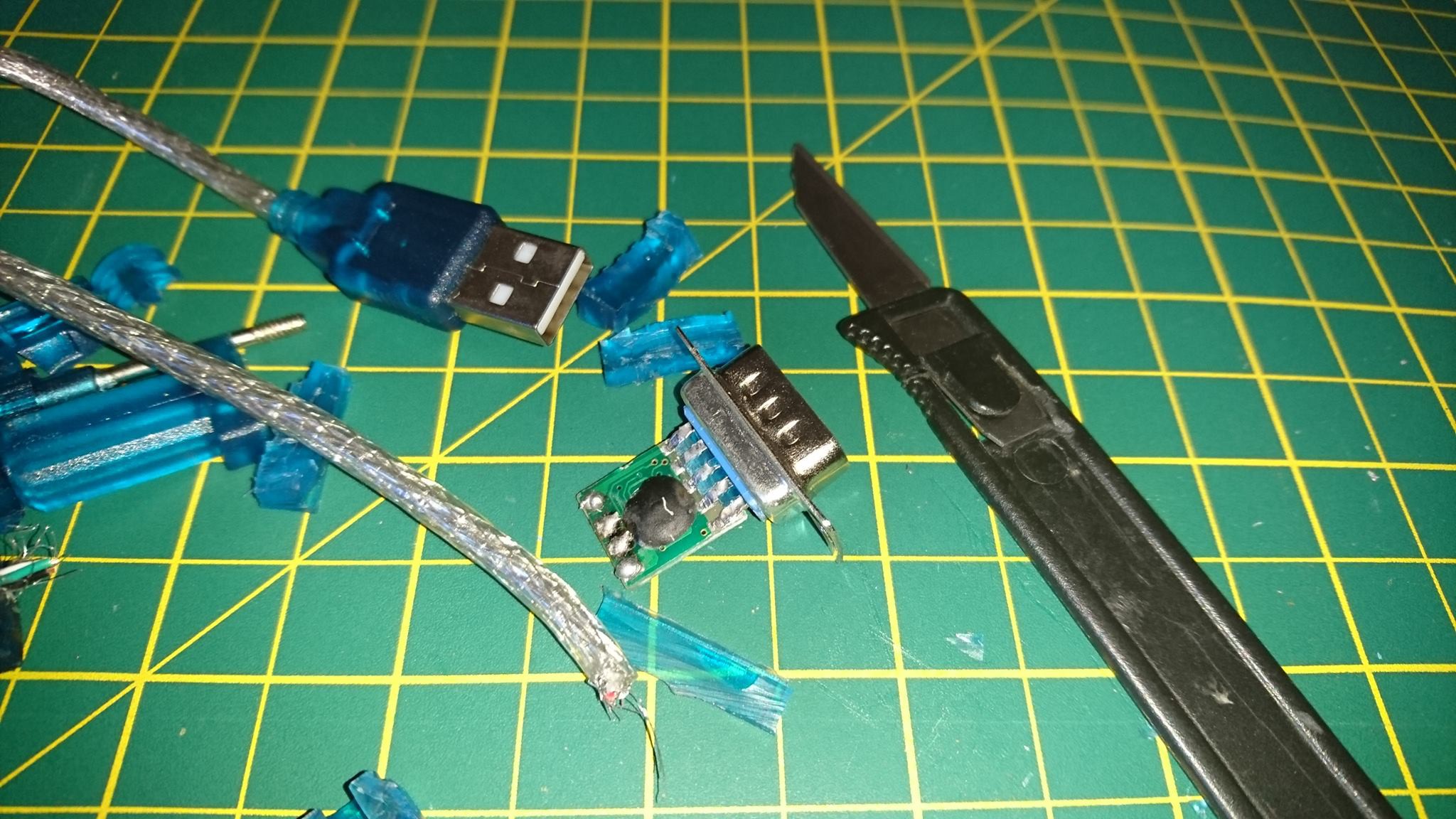
I grabbed my existing USB-to-serial cable and an unterminated Honda cable and, armed with a soldering iron and a scalpel, got to work.
Entombed inside the DB9 end of the cable is a 1cm2 PCB. And I really do mean entombed - the entire board and connections had been put in a mould which had then been filled with soft translucent plastic.
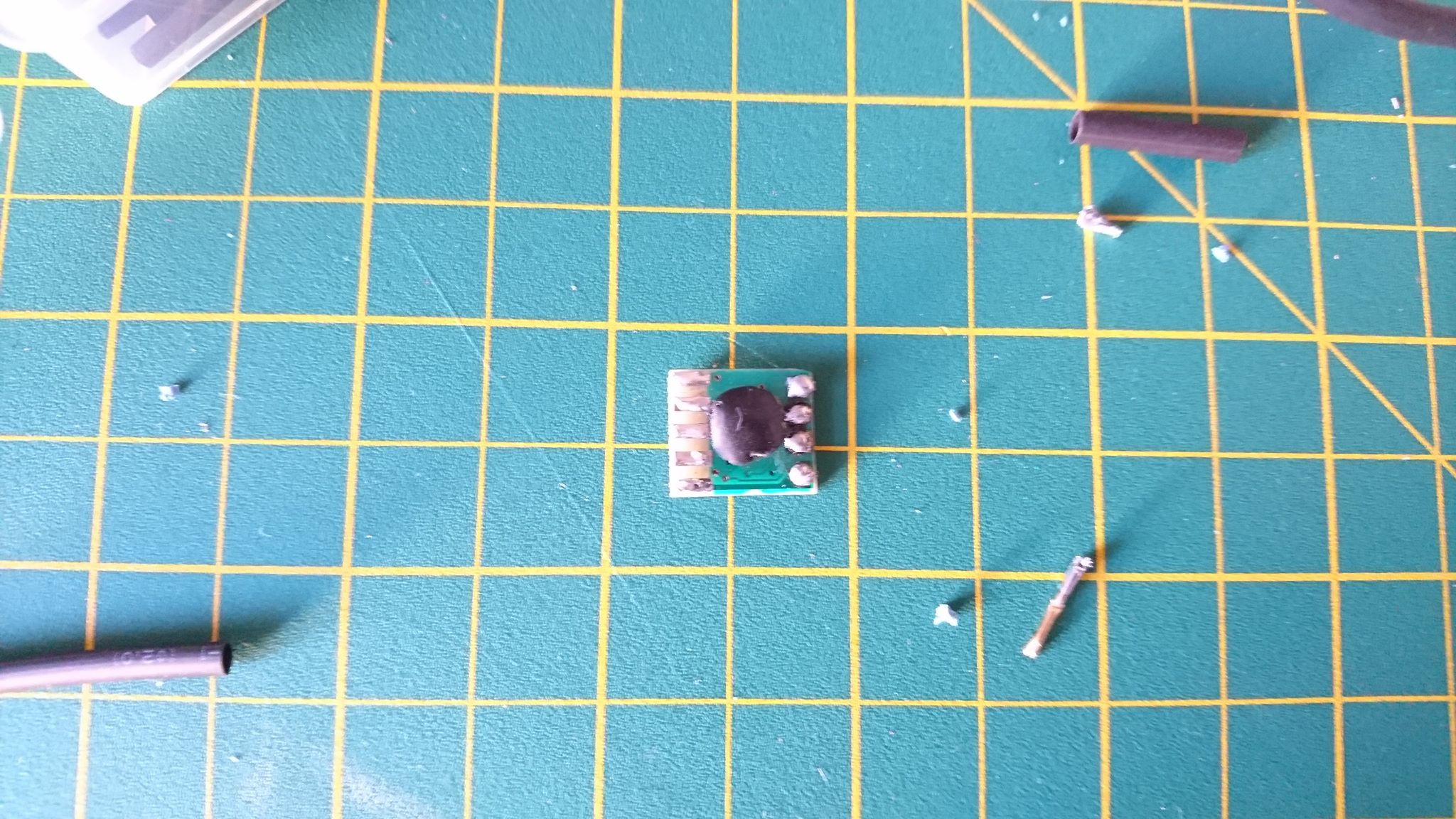
It took me a good hour or so of hacking away with the scalpel to free the board from its rubbery tomb. I also had to cut off the DB9 connector as I didn’t have any desoldering tools good enough to do the job. This is what it looked like when I was done.
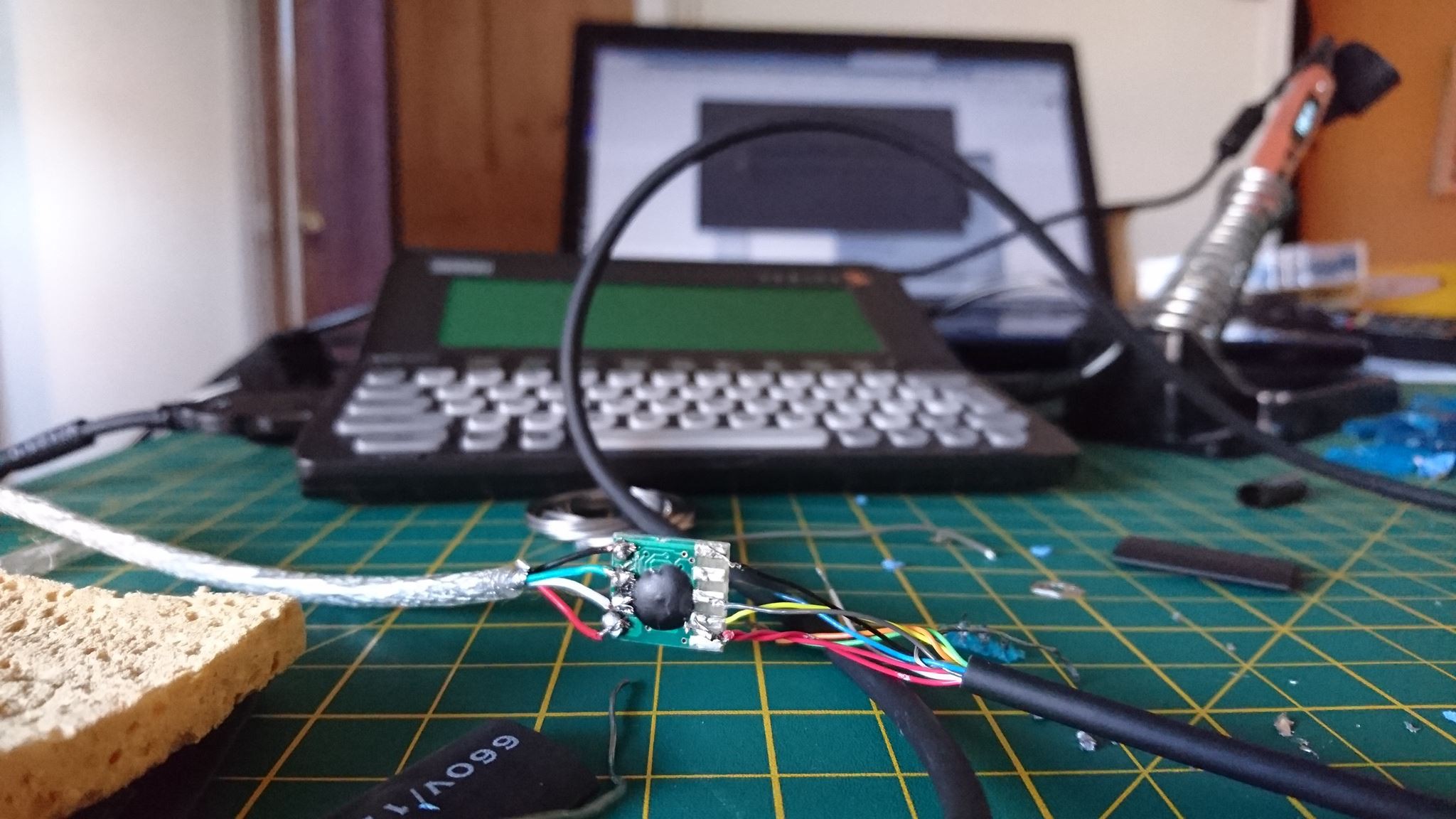
I reused the now unterminated USB cable, slipping some heatshrink onto the cable for later before soldering it to the board. I then soldered an unterminated Honda cable to the serial connectors on the board, again with heatshrink already on the cable. Here's the table with the cable's colour coding and the RS-232 pins they correspond with. (Note that the colours have changed over the years, but these colours worked with the cable I got from eBay.)
| DB9 | Honda cable colours | Honda pins | RS232 | Description |
| Shield | GND | GND | Shield | |
| 1 | - | nc | DCD | Data carrier detect |
| 2 | Yellow | 4 (TX) | RD | received data |
| 3 | Grey | 8 (RX) | TD | transmitted data |
| 4 | Green | 5 (DSR) | DTR | data terminal ready |
| 5 | Black | 15 (SG) | SG | Signal ground |
| 6 | Orange | 3 (DTR) | DSR | data set ready |
| 7 | Red/White | 7 (CTS) | RTS | request to send (= DTE ready) |
| 8 | Pink | 2 (RTS) | CTS | clear to send (= DCE ready) |
| 9 | Blue | 6 (RI) | RI | Ring indicator |
On my first attempt I had soldered the USB’s D- and D+ wires around the wrong way, so I quickly swapped those over. Once I’d fixed that, I crossed my fingers that I hadn’t damaged the board or my PC.
Luckily, I hadn’t. It worked perfectly.
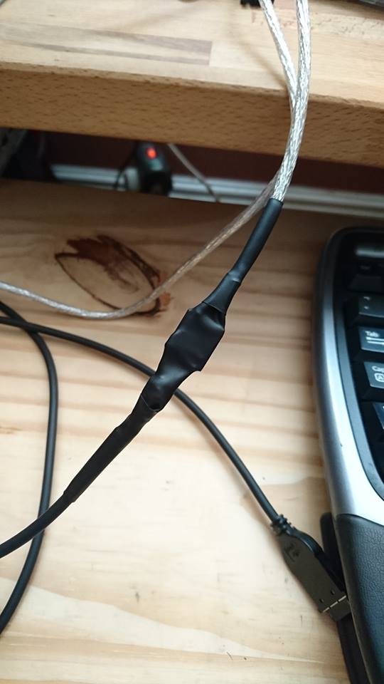
Once that was done I tidied up my soldering, put the large piece of heatshrink in place and aimed a hairdryer at it. I then moved the two smaller pieces of heatshrink and did the same.
I now have a 2m USB to Honda cable that will work on the Series 3c, 3mx and Siena, plus the Series 5 and 5mx, all for about £11.
If I did it again, I would probably find a USB plug enclosure that the CH340 board could fit inside. There is a risk of damage to the solder joints and the PCB and fitting the board inside a small box would fix that. Also, I’d really like to find a supplier who will sell me CH340 boards that don’t require me to hack away at a load of blue plastic.
Oh, and I did work out how to get MASM working, but more on that another time.
Discussions
Become a Hackaday.io Member
Create an account to leave a comment. Already have an account? Log In.