 Kenji Larsen
The handful of components are simple, a battery holder and rechargeable battery from Sparkfun, a Reactron arduino clone with radio. The button itself is a lighted SPST momentary switch.
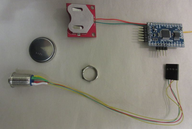
The code is what adds a little flexibility to this setup. The switch could actually be any of a choice of switches, with numerous poles , tri-state, latching, etc. The code is what decides how the switch behaves. This particular SPST momentary is tied to a digital input and a digital output, where the digital output is pulsed. When the switch is closed, the input sees a pulsed signal. This allows a bit of safety, we know that the switch is not accidentally open or shorted - or if it is, we can ignore it or take an appropriate action.
In addition, this switch has a blue LED built in. That LED is also tied to a digital output, and the code will light the light if and only if all the conditions assigned to enabling the switch are true. this is how you know that all the dependencies are online and ready to go.
Technically, this could be considered an Integron, a human interface device within the Reactron network. It has human input (button press) and output meant for human eyes (light). While that is true, it is not very complex as far as interaction goes. The light is basically an “on” light, indicating operational status, and the button is just a bit (for this switch) or set of bits (for more complex switches). The important thing is the state of those bits. So this is a Collector - it collects the data, which are the state of the bits (in this case, just the one).
By itself, it does nothing. A bit turns on and off, completely useless if it isn’t assigned some action to trigger by another node that is monitoring its state (or receiving its state actively and asynchronously - both modes are available). But that too is the strength and the flexibility - it can be assigned to anything, and it can have a one-to many, many-to-one, or many-to-many relationship between monitoring node(s) and actioning node(s).
In the house of the future, perhaps all light switches will be these low-voltage, wireless, data-only devices. Not this hardware, but perhaps something even more low-power with a tiny sealed battery that would last thirty years. (But the concept is the same, those would just be inevitable refinements.) This way, you don’t have to have mains wiring all over the place, every place you need what is essentially just a human interface. Power could go just from the source to the light (or other load) with a data interpreter in between, monitoring the bits in these switches. Even today, these switches can be made completely flat, with thickness on the order of a millimeter - battery, chips, perhaps a capacitive sense switch - as a sealed single data-addressable unit, these can be placed anywhere on the wall or not on the wall. Want to hang a different picture but the switch is in the way? Just peel it off and move it over a bit. Gang several together for two-way, three-way, or completely customized behavior.
In my version here, the electronics are basically flat, and the switch is not, because it is just an inexpensive panel-mount momentary switch. I have mounted this switch inside the top cover of a water tank, with a Lexan shield in between to protect the electronics from any accidental moisture.
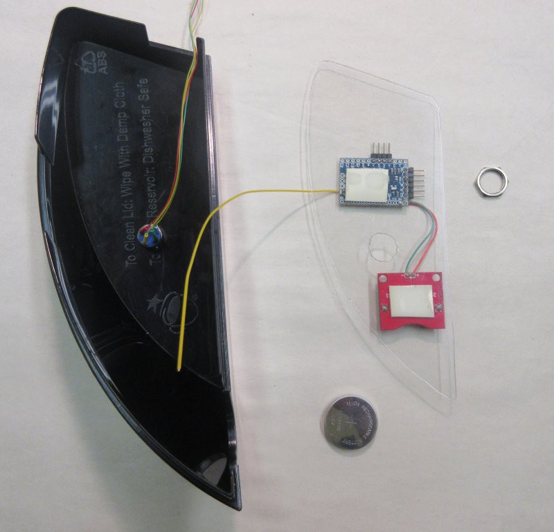
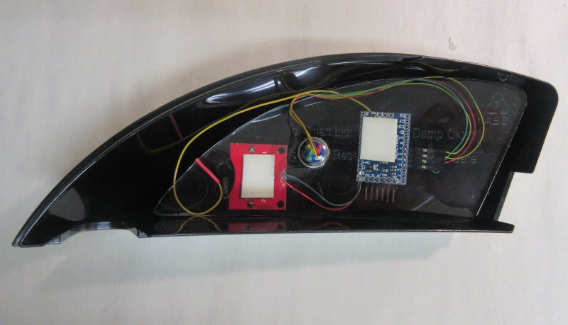
This is the cover to the water tank of my coffeemaker.

The function is to expose its state to my automatic water pump that fills the coffeemaker when the tank is low. This provides a manual “run the pump” signal, in case I want to fill it higher, or just purge the line. It occurs to me that since the switch unit is in the cover, I should put some electrodes there that hang downward, such that it creates a limit switch to prevent overfilling.
Currently the coffeemaker itself has a switch to detect the low-water condition, but nothing built in for too-much-water. Well, maybe I will get to that someday. This would effectively just be another switch, another pole, another bit, nothing more, in the switch unit. The monitoring node can make decisions based on [is the mechanical button pressed] and [is the too-much-water level tripped], and is thereby a Processor.
The actioning node is the water pump. The monitoring may be done on the pump unit’s Reactron microcontroller, even though it is a completely separate function from the actioning - it’s a good choice here, the switch is not general purpose, now that it is built into a water tank cover, and the pump is tied to filling that tank. The main point, however, is that it need not be on the same node at all - Collector (switch) -> Processor (monitoring and decision-making node) -> Material transporter (pump). These can all be separate. They could also all be the same. I could have just run wires up from the pump to the switch in the cover, and put everything on that one microcontroller.
But, I like the switch better wireless, as it does not physically complicate taking the cover off and putting it back on. And I like it better code abstracted and isolated. If one thing breaks, all three things don’t break. Since in this case there is a single action tied to the switch, and that is to run the pump, it’s OK to put the decision making and the actioning together. The pump actually already has Processor code on board, it is checking the state of the low-water status on the coffee maker node.
So, three separate nodes. If the switch node breaks or runs out of batteries, it is of little importance, the other two are plugged in and automatic filling will still occur. If the pump node breaks, the switch won’t trigger anything, but I may have to hit the manual air pressure pump lever, if I need more water.

If the coffee maker node breaks, the other two don’t matter, and I can still operate the coffee maker itself manually. If the coffee maker is broken, well, now we have an emergency!
But that would have been the case with no nodes at all…