0%
0%
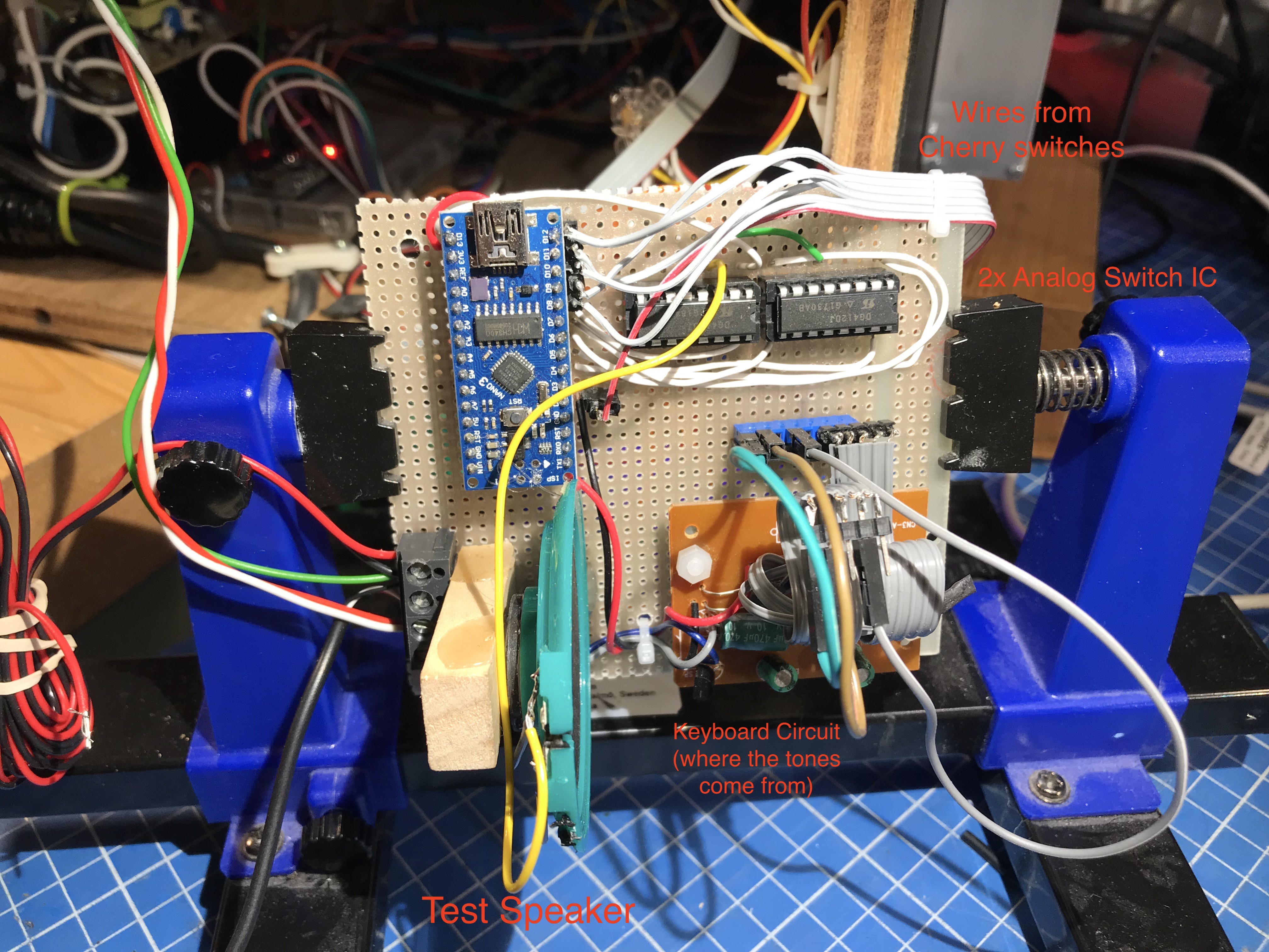
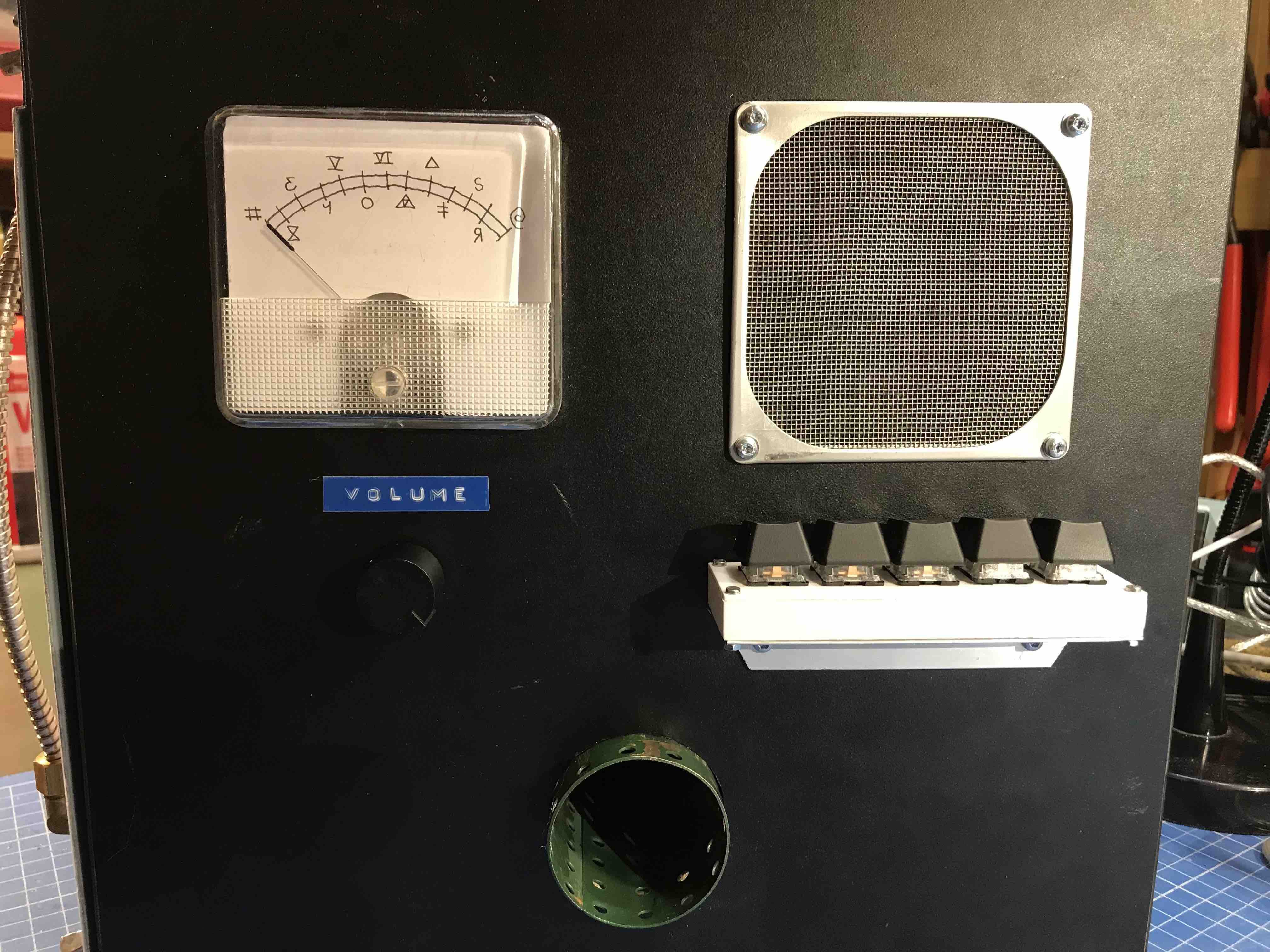
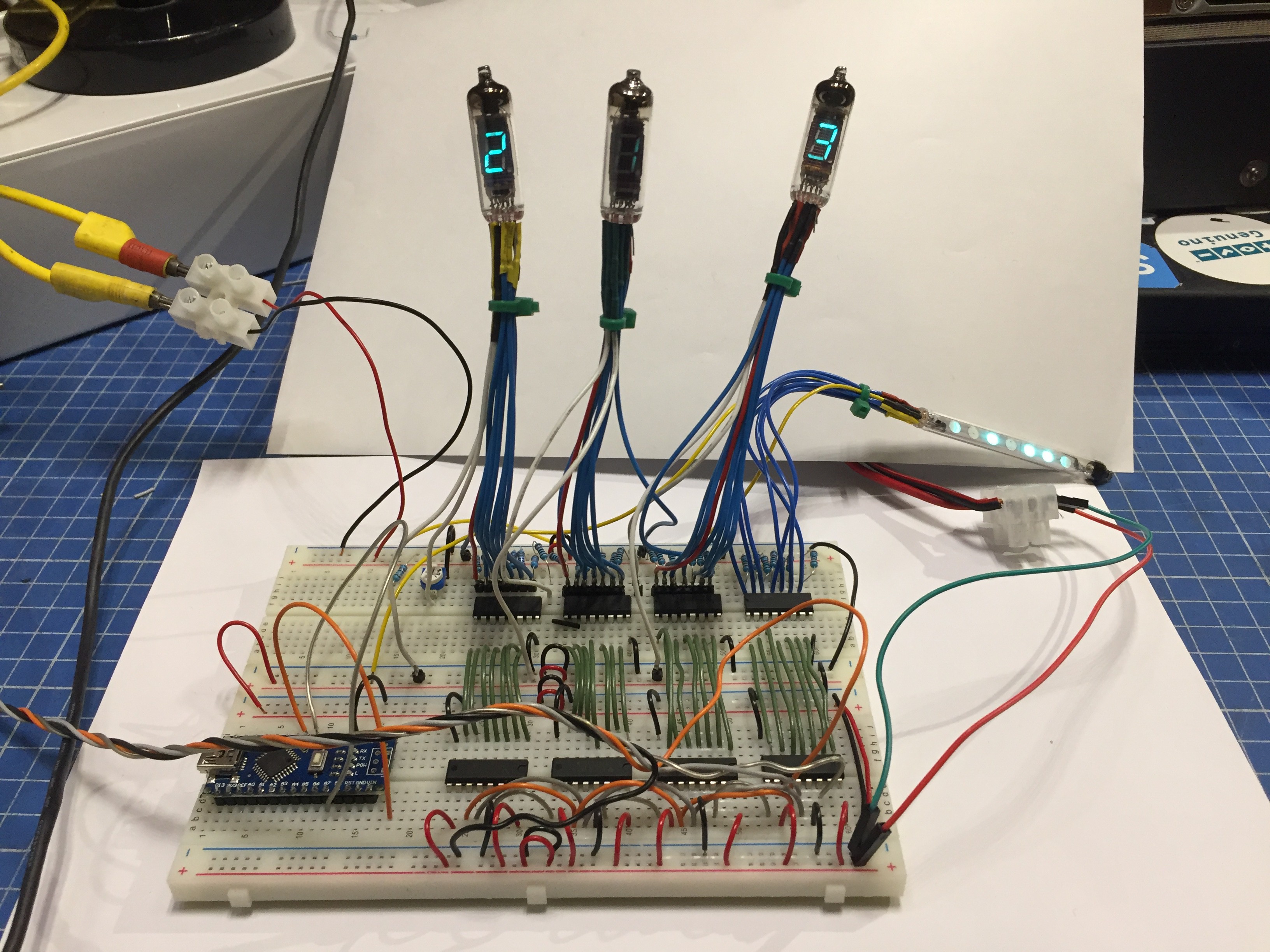
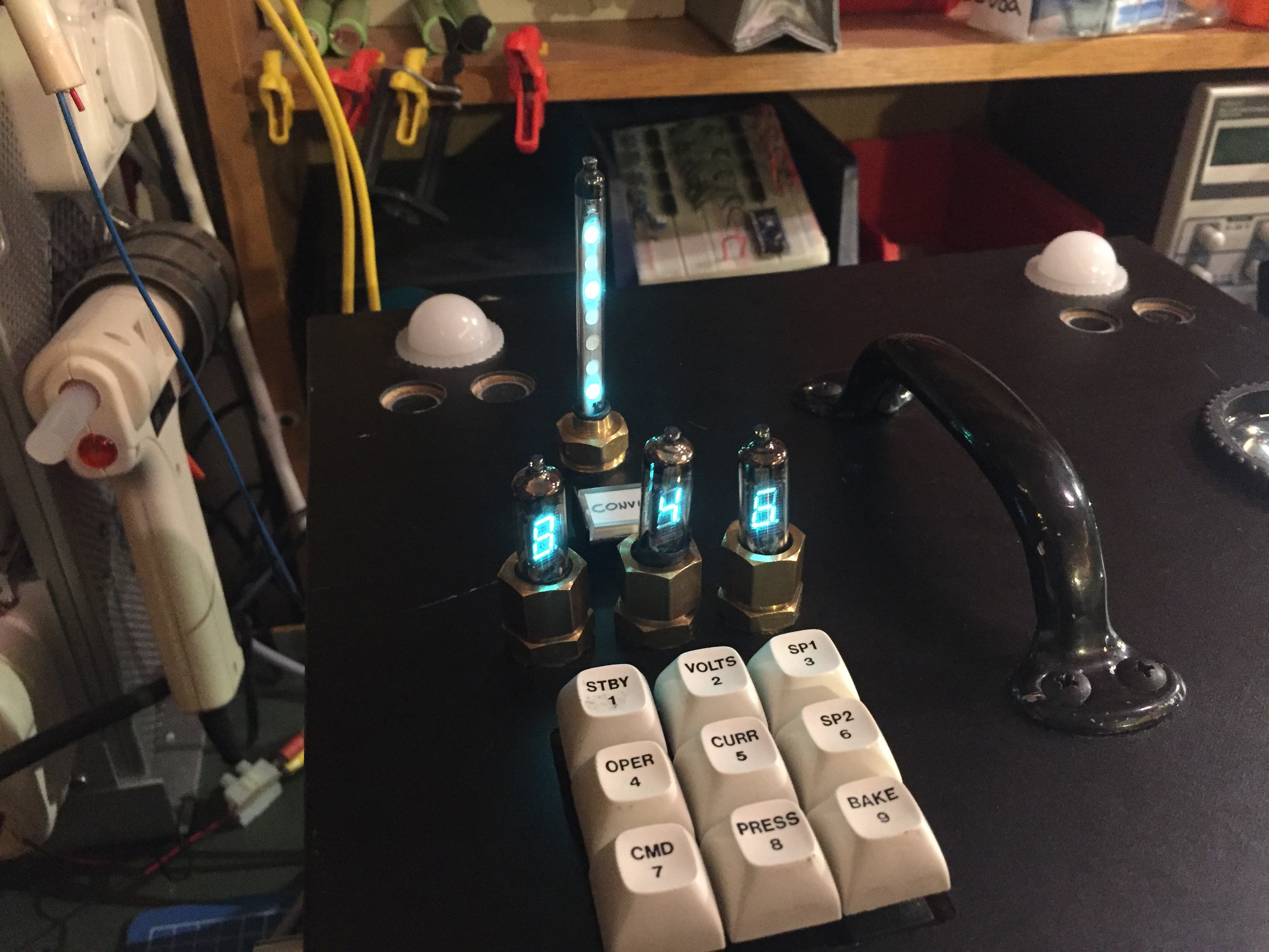
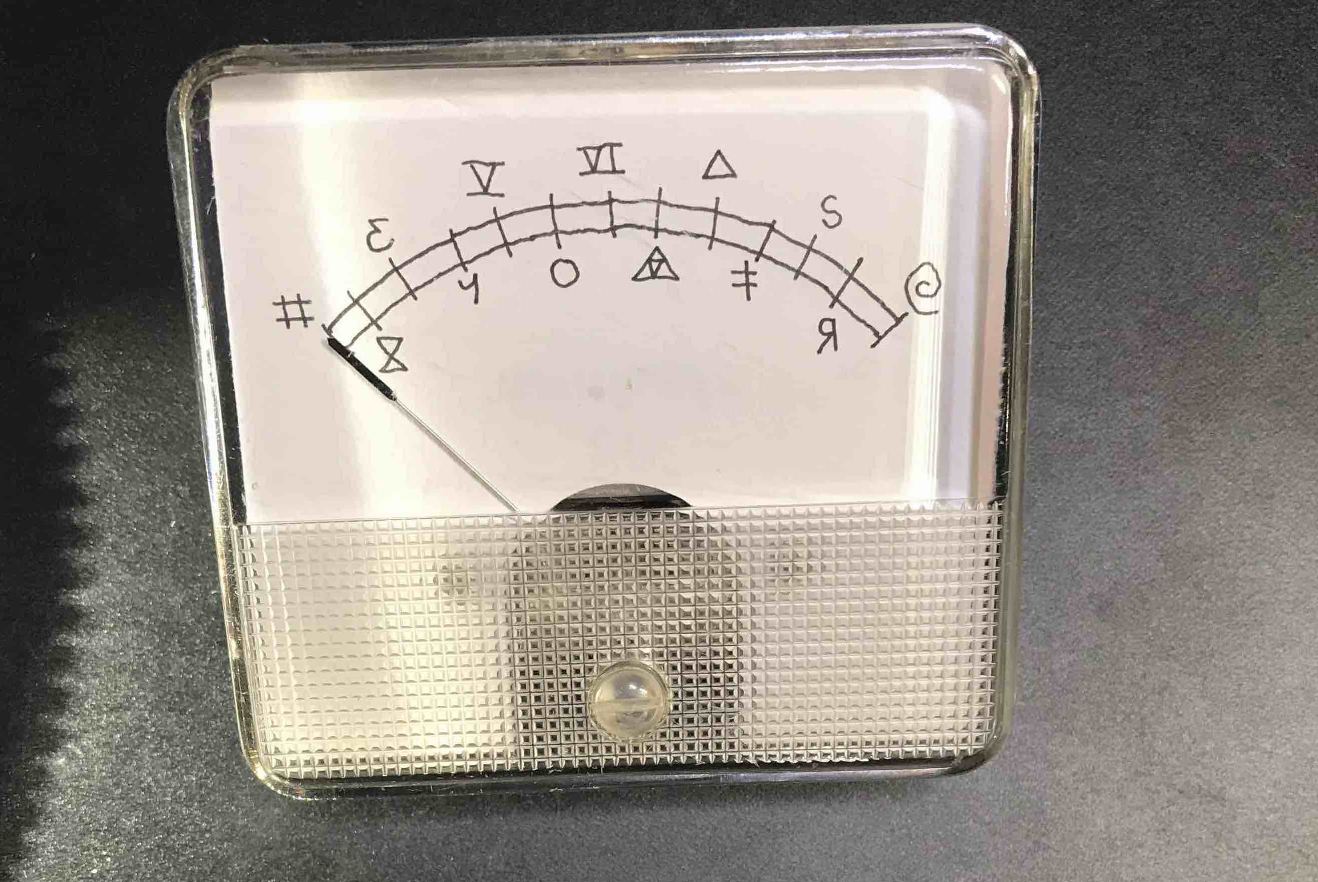
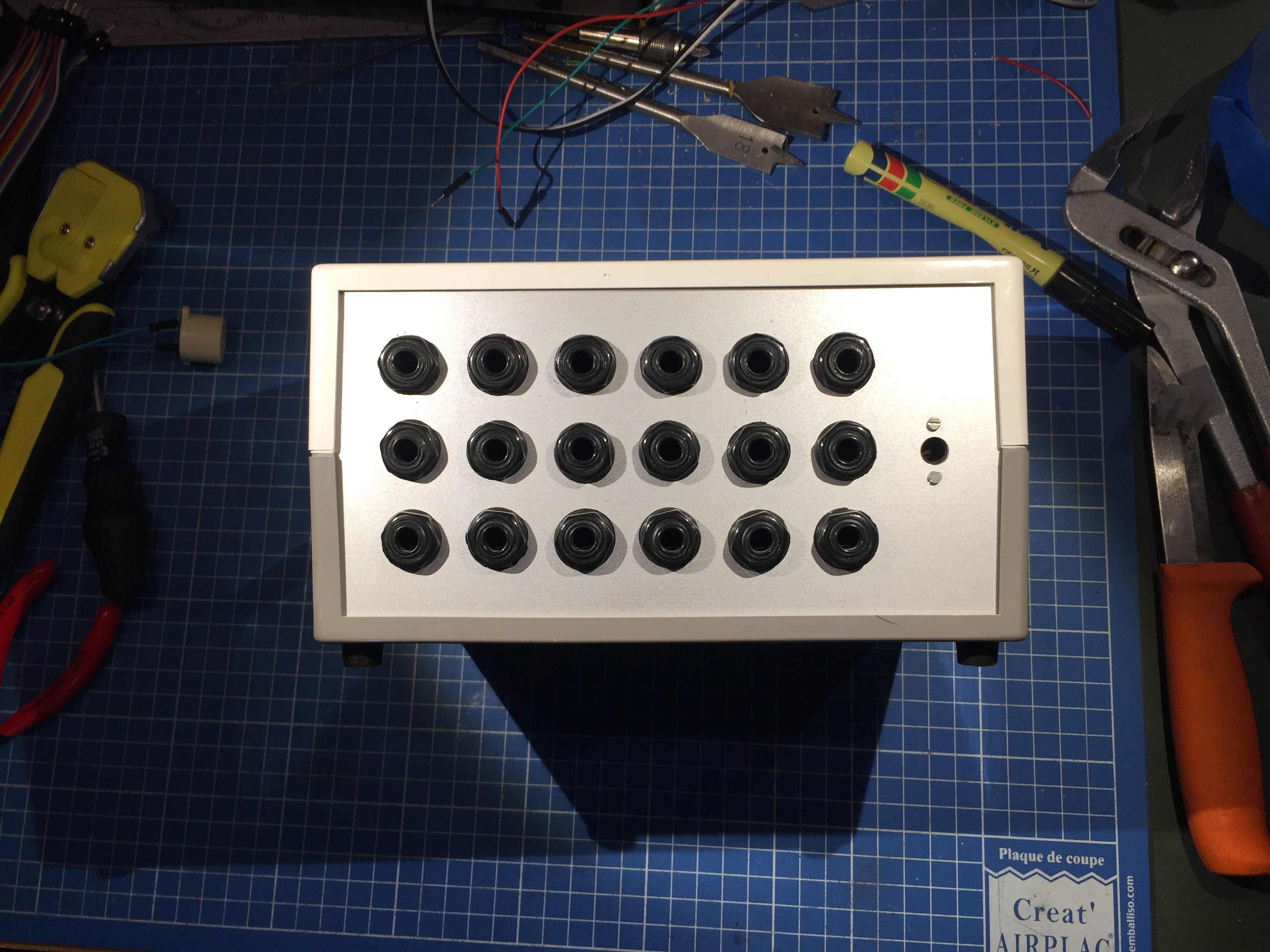
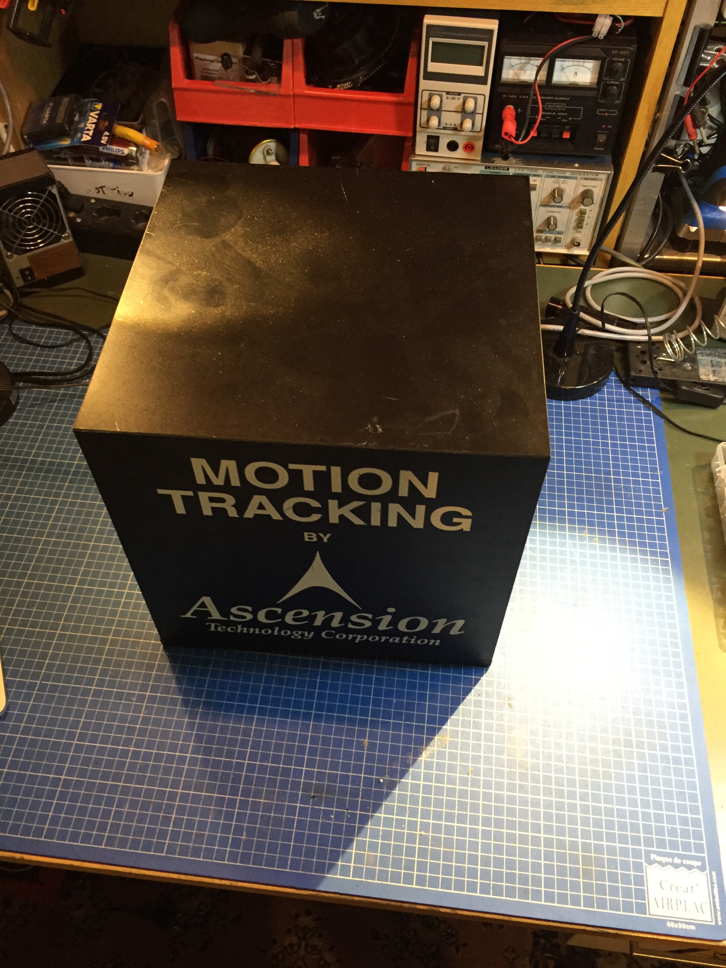
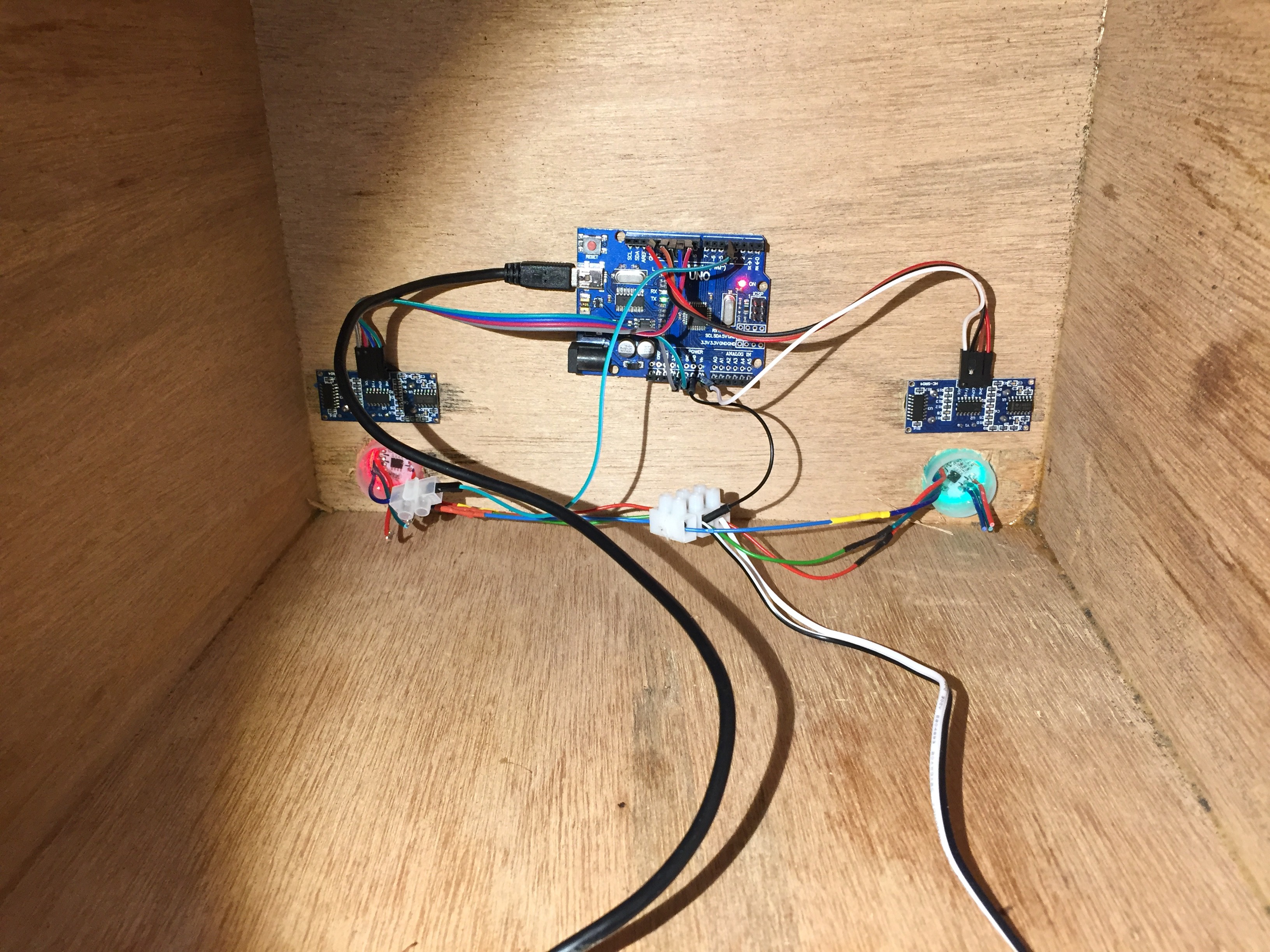
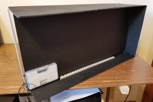
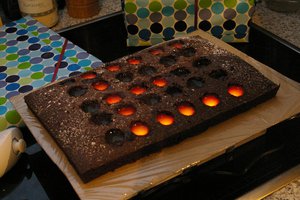
Escape Room Box Puzzle Game
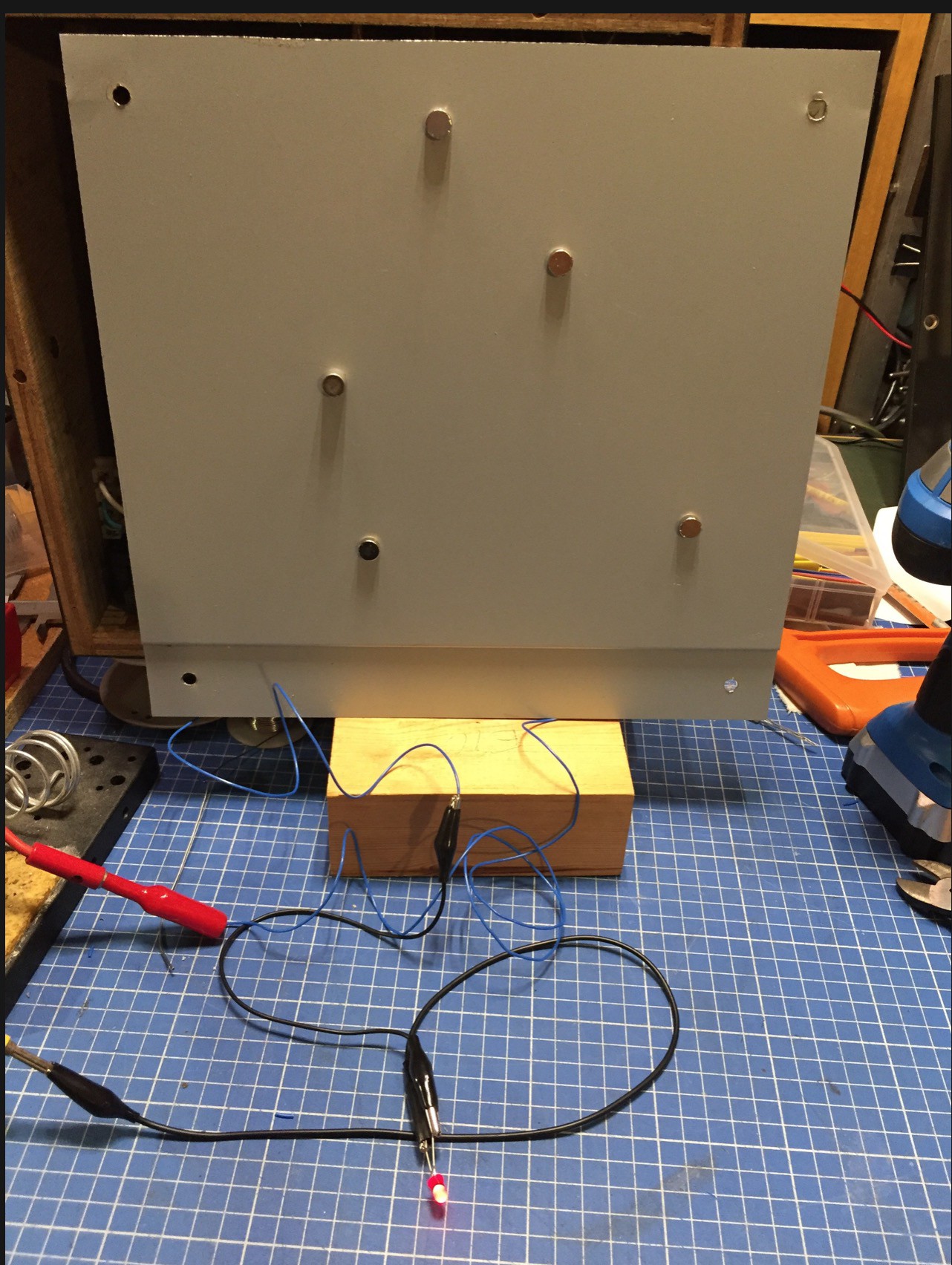
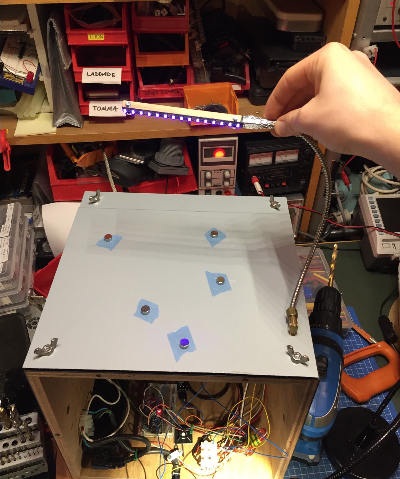
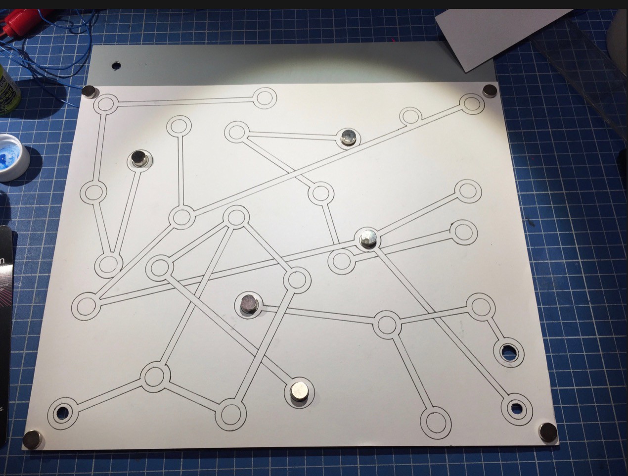
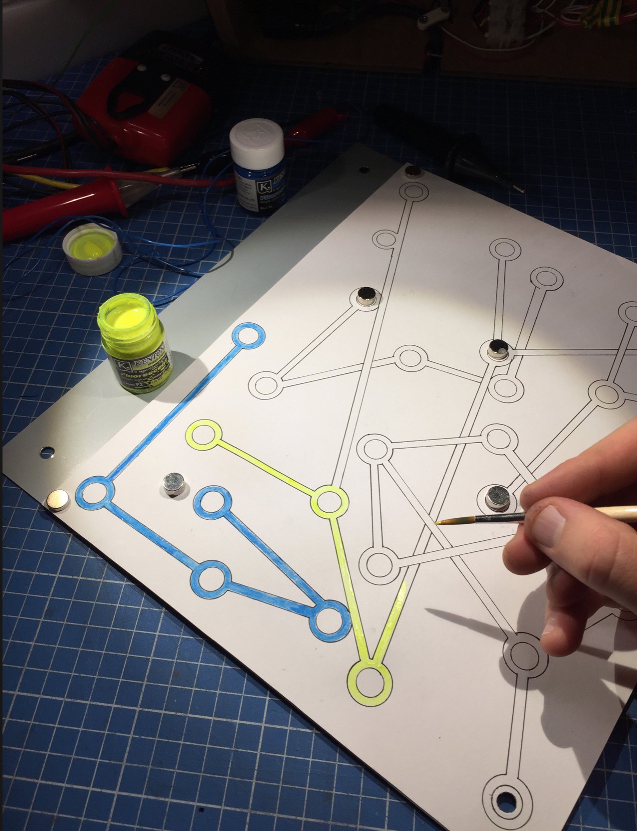
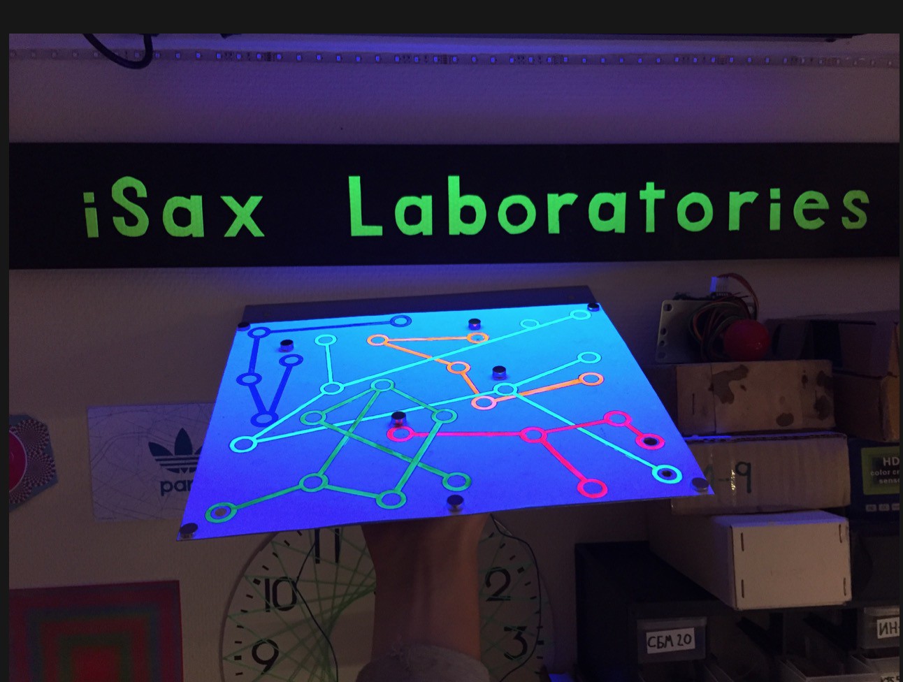
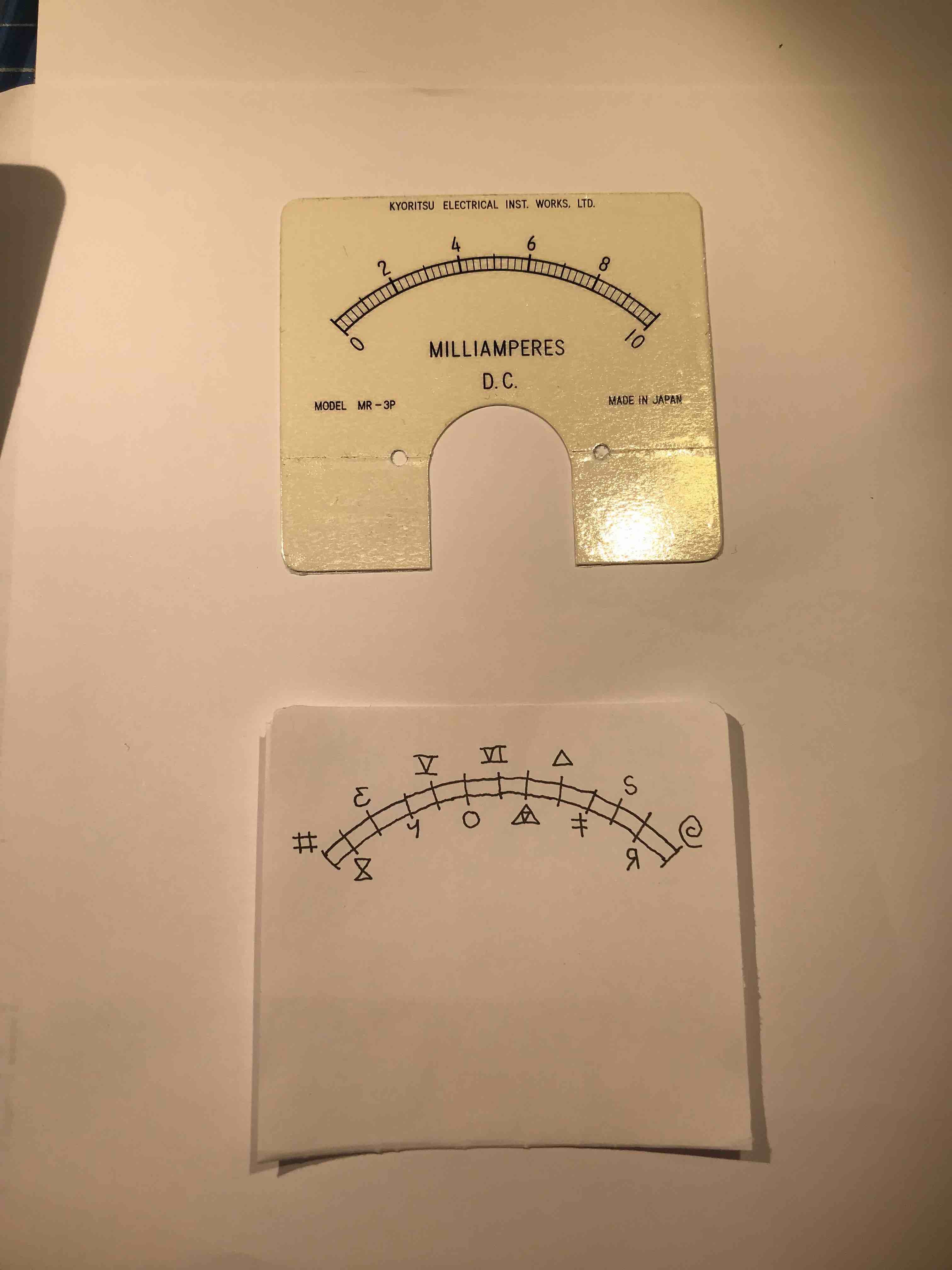
I don't have a room to spare for an escape room game so I made this box instead. Several exciting tricky levels to overcome!
 iSax
iSaxBecome a Hackaday.io member
Already have an account? Log in.
Just one more thing
To make the experience fit your profile, pick a username and tell us what interests you.
Pick an awesome username
hackaday.io/
Your profile's URL: hackaday.io/username. Max 25 alphanumeric characters.
Pick a few interests
Projects that share your interests
People that share your interests


 Bob Baddeley
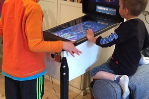
 treibair
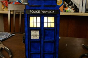
 Adam Sifounakis