 Dan Julio
I did a lot of online research when I started this project and pored over earlier efforts by Julian Ilett, Debasish Dutta, Lukas Fässler, kjoehass and Ant. I appreciate their efforts to document their work and their great designs, and sometimes failures. It's in that spirit that I've created this project entry. The actual technical documentation is in my github repository. Currently it has supporting documentation and software.
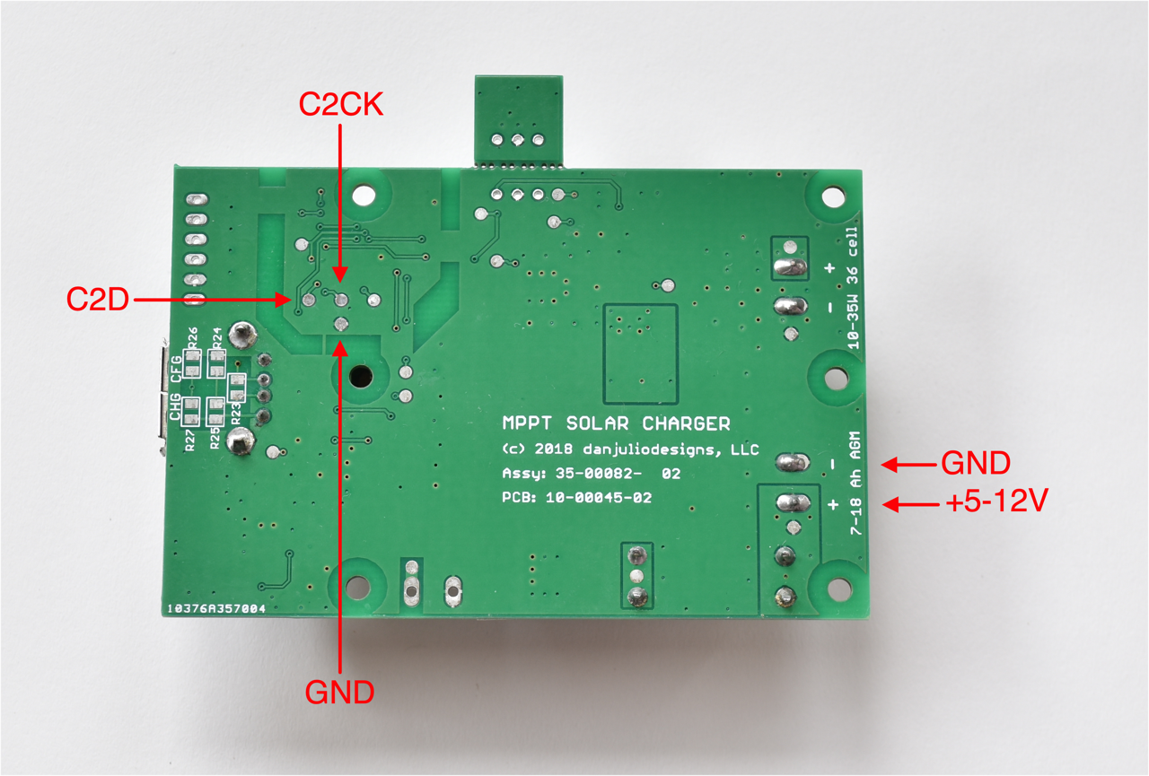
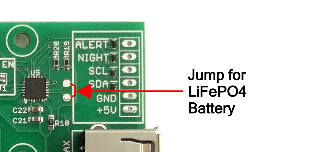
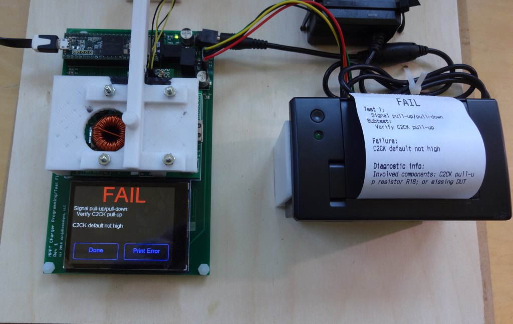
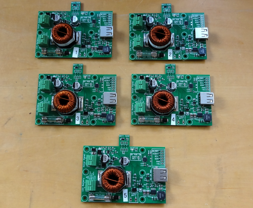
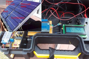
The MPPT Solar Charger is a combination solar battery charger and 5V power supply. It manages charging a 12V AGM lead acid or LiFePO4 battery from common 36-cell 12V solar panels. It provides 5V power output at up to 2A for systems that include sensors or communication radios (although designed for average power consumption of 500 mA or less). Optimal charging is provided through a dynamic perturb-and-observe maximum power-point transfer converter (MPPT) and a 3-stage (BULK, ABSORPTION, FLOAT) charging algorithm. A removable temperature sensor provides temperature compensation. Operation is plug&play although additional information and configuration may be obtained through a digital interface.
- Optimized for commonly available batteries in the 7-18 AHr range and solar panels in the 10-35 Watt range (larger panels will work)
- Reverse Polarity protected solar panel input with press-to-open terminal block
- Fused battery input with press-to-open terminal block
- Maximum 2A at 5V output on USB Type A power output jack and solder header
- Automatic low-battery disconnect and auto-restart on recharged battery
- Temperature compensation sensor with internal sensor fallback
- Status LED indicating charge and power conditions, fault information
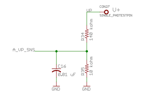
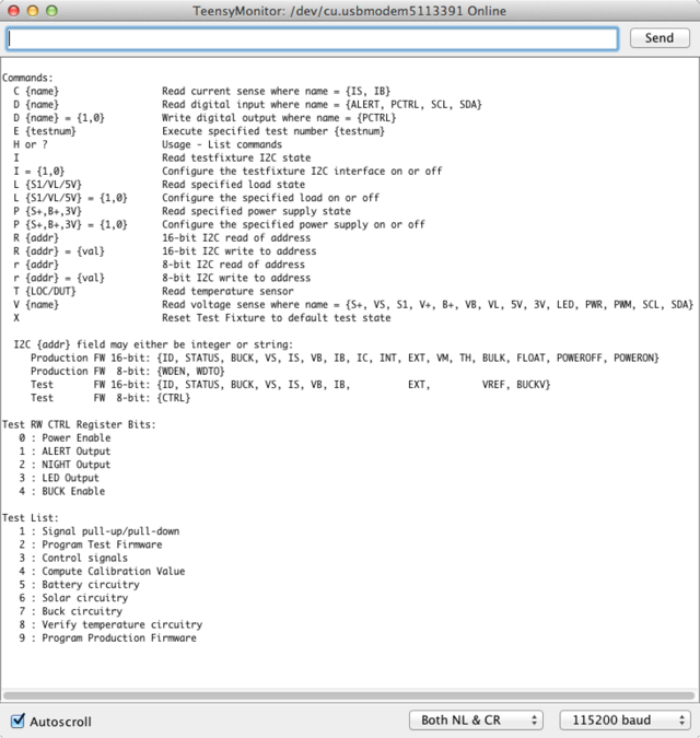
- I2C interface for detailed operation condition readout and configuration parameter access
- Configurable battery charge parameters
- Status signals for Night detection and pre-power-down alert
- Night-only operating mode (switch 5V output on only at night)
- Watchdog functionality to power-cycle connected device if it crashes
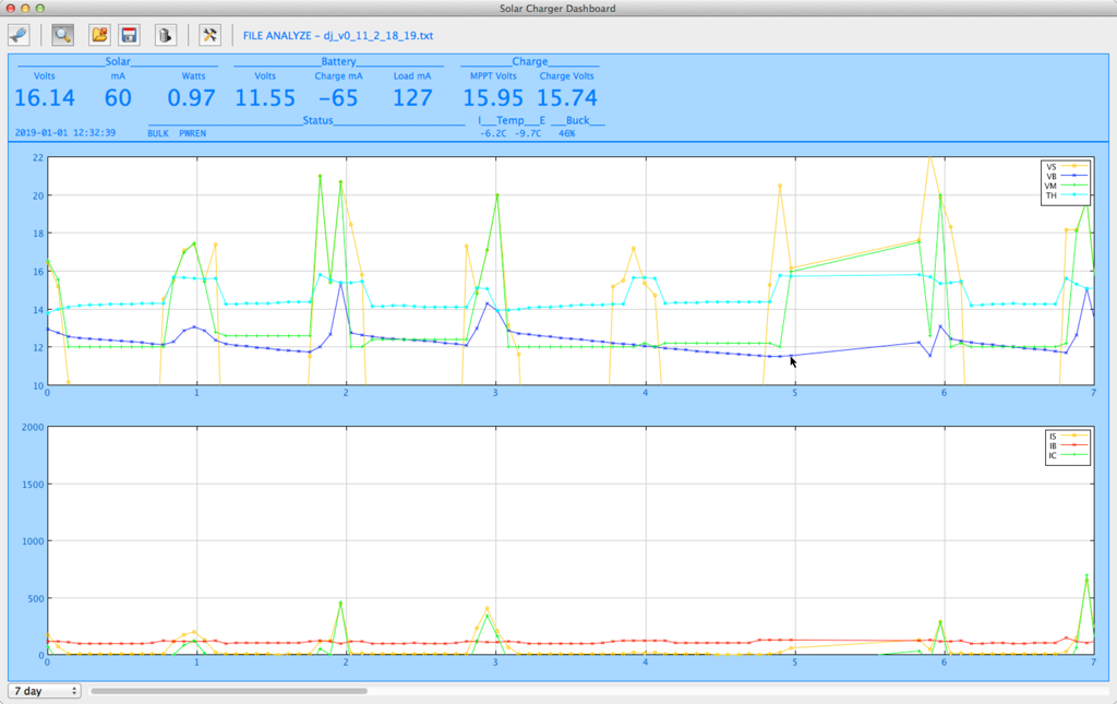
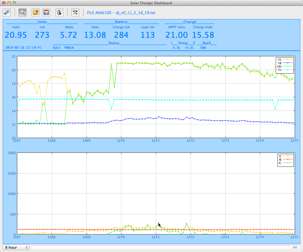
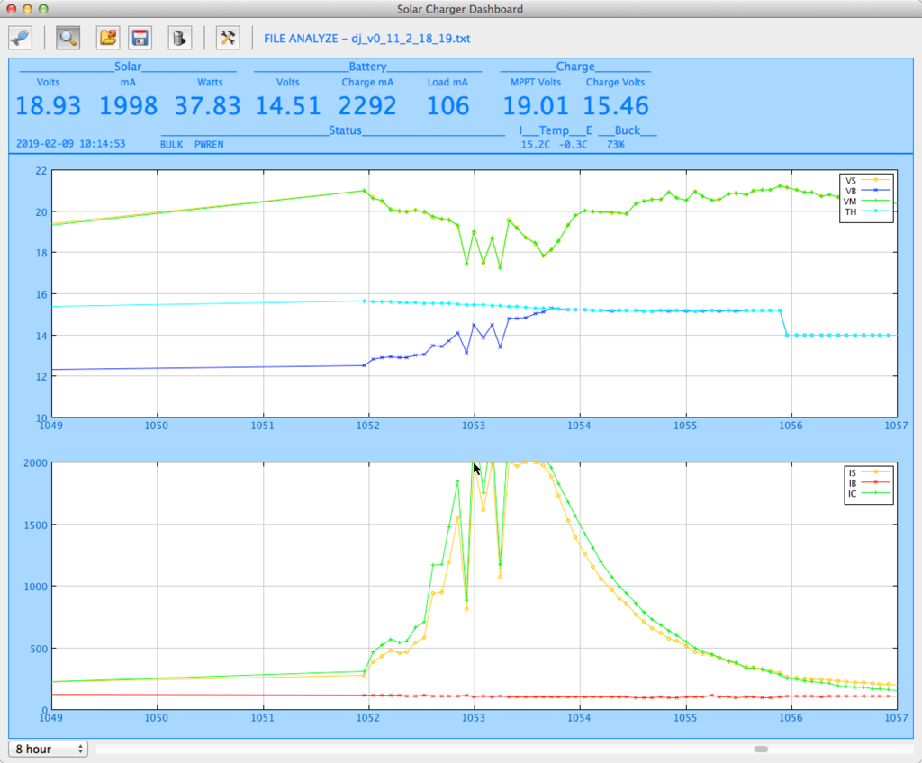
Software support for the MPPT Solar Charger includes an arduino library (which also compiles on Raspberry Pi), a daemon program designed to run on the Pi enabling other software to communicate with the charger and also to log data, a desktop application for monitoring and graphing log data. Eventually I'd like to also add a simple web-server to allow easy remote access.
I envision this device being useful for all manner of remote sensing or monitor applications, or for remote webcams, or even to power a set of garden lights or provide solar USB charging power.

 Tobias
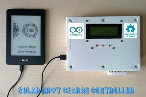
 Open Green Energy
 rawe
rawe
 Patrick Van Oosterwijck