 Dan Julio
My choice of an inexpensive micro-controller has a cost. This product has firmware that will probably never be upgraded since there is no facility to easily load new code (no interface and not much space left over for a bootloader). So the release firmware needs to be pretty close to perfect. It helps that this isn't a very complex device and I tried to make architectural decisions to mitigate entire classes of problems. Still, with about 4300 lines of C, there are bound to be bugs. And there have been. Initially, of course, I found lots of simple bugs that were also pretty easy to find and fix. After the system was pretty functional I executed a test plan to verify all major functionality under the main operating conditions. This found a few more issues, things like incorrect status bits in a register. Then I started testing as much as possible in real-world conditions - which for this system meant devices running for extended periods on solar power in as many different conditions as possible.
That's when things got interesting. Throwing wildly varying solar conditions, battery voltages and conditions, temperatures and loads into the mix started uncovering the corner cases. Slowly. The best tool I have had is the ability to log all the main parameters via the daemon running on a Pi because some of the corner cases didn't crash or harm anything, they just made the system less efficient.
Recent winter testing just uncovered one of these corner cases. It was exposed because the desired MPPT voltage was less than the desired charge voltage for the battery. I found it looking through data from a cold overcast day.
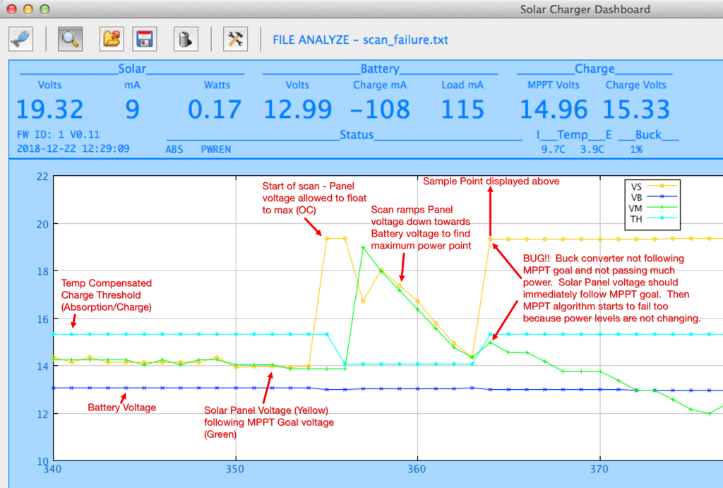
The firmware periodically executes a scan to find the current maximum power-point because there is a slight risk of the P&O MPPT algorithm wandering off from the ideal maximum power-point (less risk in a design like this with one small solar panel than with a large-scale system with larger or multiple panels where shading can cause local power minima and maxima). After one of these scans I saw that the buck regulator was not operating correctly, in fact barely operating at all, and was not tracking the MPPT which then caused the MPPT algorithm to fail because there was no change in power as it adjusted the MPPT voltage goal. In absolute terms, this bug was not severe because it occurred at a point where the system was producing relatively small power and was corrected by the next scan ten minutes later. I hadn't seen it before (although it may have happened) because it would only manifest when the light was low leading to a low MPPT power-point for the panel and the battery charge threshold was high because the charger was in the Bulk/Absorption phase and the low temperatures caused the compensated charge voltage to be high (15.33 volts in this case). The actual bug occurred because at the end of the scan the charger attempts to initialize the buck converter PWM value based on a simple CCM calculation representing the fraction of the output voltage to input voltage:
pwm = MAX_PWM_VAL * OutputVoltage / InputVoltage
where the MAX_PWM_VAL is 1023, the OutputVoltage is the desired charge voltage and the InputVoltage is the MPPT goal. The buck control logic will then, over time, adjust the PWM value to the actual ideal value but this is a good starting point for most cases. My problem was that the InputVoltage was less than the OutputVoltage and I didn't check for that. The 16-bit variable holding the 10-bit PWM value overflowed 10-bits. The actual PWM peripheral only looked at the 10-bits so was set to a small value. However the code worked on the 16-bits and the buck logic wouldn't allow a change because it was already over the maximum PWM value. The fix is easy. In this case the PWM should be set to the maximum value essentially directly connecting the panel to the battery for these low-light, low-power conditions. It's the most efficient too as there are no switching losses. I had never assumed that the MPPT voltage would be less than the charge voltage.
There have been a few other interesting corner cases which is why I want to test through the winter season before releasing the firmware in the product.
Early on, the scanning process showed another, potentially harmful, anomaly during the summer season with plenty of high intensity light. Lead Acid batteries have an interesting characteristic where, when they are nearly charged, dumping a lot of current into them causes their voltage to shoot up. Normally the buck converter control algorithm limits the power transfer for several reasons, first to hold the solar panel voltage to the MPPT goal, second to hold the battery voltage to at or below the charge threshold and finally to limit the maximum current flowing through the buck circuitry. However the limits on voltage need to be disabled during scanning to ensure we are seeing the true maximum power-point. This caused the battery voltage to shoot up way past the charge threshold when it was nearly charged but the system was still in the high-threshold Bulk or Absorption charge states and the panel could produce a lot of power. The temporary high voltage probably wouldn't harm the battery (I don't know about repeated cases) but I thought there was a risk that it would exceed the 18V maximum input of the 5V buck converter or a customer load applied directly to the battery output. The fix for this was simple too. The system suppresses the scan activity whenever the buck converter is limiting since the fact it is limiting means that the system doesn't have to operate at the maximum power-point. There's no need to find that until solar power has fallen off to the point where the system isn't limiting the power transfer.
Another interesting corner case occurred when the system would shut down the load for a depleted battery. When the battery voltage falls below a configurable minimum (default 11.5V) the system alerts the load with a one minute warning and then powers off the 5V output until the battery is charged to another configurable set-point (default 12.5V). However I saw that an old battery will bounce back once the load is removed temporarily exceeding the restart set-point, which restarted the load immediately. The system then went through several cycles of power-down/power-up until the battery was sufficiently depleted so the bounce didn't restart the system. The fix for this wasn't immediately obvious but I settled on having the system see the battery charge for at least an hour before restarting if the battery voltage was above the restart set-point.
Currently I am trying to track down a potential issue that, in almost a year of testing, I've seen only twice. The daemon program that runs on the Raspberry Pi can automatically shut the Pi down in a controlled fashion if it sees an impending low-battery shutdown alert from the charger. It senses this by reading the STATUS register once per second. The power management code is designed to switch off 5V power one minute after signaling the alert in order to give a system time to do a controlled shut down. However in both cases the daemon initiated a shut down but the charger did not kill power. In fact log data shows a charged battery voltage so I don't understand how the alert is being generated. I've done testing reading the STATUS register repeatedly without ever seeing a read failure and tested the code path related to alerts and shut downs without any failures. I did add code to require a continuous low-battery condition for 1 minute to prevent a momentary droop in battery voltage from triggering a premature shutdown but I saw the failure again last week after this code was added. So now I've instrumented the daemon to dump a bunch of register values if it sees the alert before shutting down. We'll see...
Discussions
Become a Hackaday.io Member
Create an account to leave a comment. Already have an account? Log In.