 Dan Julio
Putting control of a device like this into firmware requires accurate measurements of the data required by the algorithms and probably the area I spent the majority of time while testing with prototypes was getting reasonably accurate voltage and current measurements from the micro's ADCs. This is because values fluctuate greatly as the buck converter (or PWM) switches on and off, especially the current values. Incorrectly sampling these lead to wildly incorrect measurements. In fact, this was a question I had about some of the other charger solutions I saw. There didn't seem to be much, if any, signal conditioning or filtering.
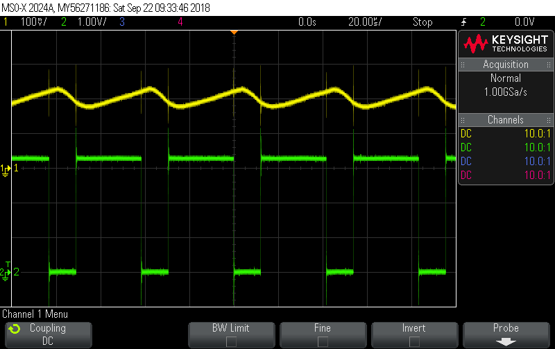
I use a simple voltage divider (1/15) to measure solar and battery voltage and a TI INA180 high-side current sense amplifier (generates a voltage equal to 20 x drop across the 0.025 ohm sense resistor). The MPPT buck converter runs at about 24 kHz while the 5V output buck converter runs at about 500 kHz. A typical output of the Solar current sense amplifier (along with the MPPT buck converter PWM signal in green) is shown below.

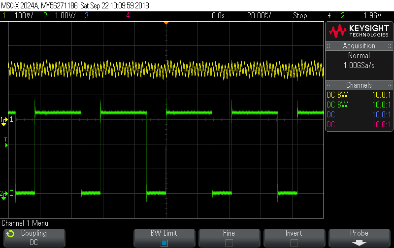
The signal has a huge variation as the main inductor charges. A very fast sample rate (multiples of the PWM frequency) could be used to process the signal completely in code but that is way beyond the capability of most inexpensive micro-controllers. Low pass filtering will work too but INA180 amplifier stability sensitivity makes it more difficult to build an inexpensive low-pass filter for the relatively slow solar buck (trade-off of required impedance for the ADC and load on the INA180). The current prototype uses a combination of a simple RC low pass filter with a roll-off at around 16 kHz and a low-compute requirement software filter driven by a 1 kHz sample rate. The output of the RC low pass filter provides the ADC with the following signal for the solar current (the most variable of all signals).
The software filter implements a low frequency bandwidth for the current of about 3 Hz and 20 Hz for the voltage signals.
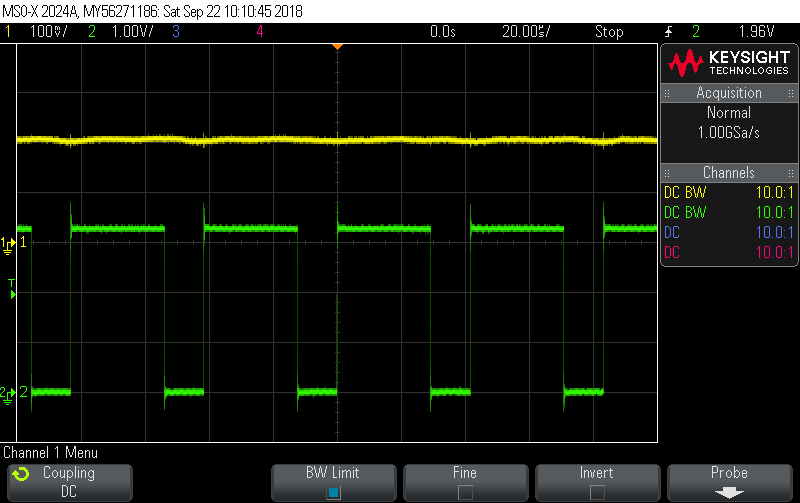
The higher frequency battery current signal is mostly cleaned up by the RC filter.
The original PWM charger prototype had an interesting issue measuring the solar voltage. When the transistor is switched on the panel voltage is dragged down to the battery voltage (minus the voltage drop across the transistor). When the transistor is switched off it floats back toward the open-circuit voltage. The firmware needed the open-circuit voltage to make decisions so periodically it turned the PWM off for a measurement interval and took a reading at the end of the interval when the panel voltage had recovered (the PWM frequency was about 500 Hz). The prototype didn't measure the solar voltage with the transistor switched on which would have been necessary to compute power. It did, however measure the current and battery voltage values after the PWM period started and the transistor was switched on. This was not ideal either because the current and voltage levels changed during that time. Unfortunately I did not take any scope images to illustrate. To get more accurate readings would have required a burst of reads during the on-time of the PWM period and an average computed for those. The higher frequency of the MPPT buck converter actually makes the problem easier. I'm guessing that commercial PWM chargers like those made by Morningstar (e.g. SunKeeper series) only try to regulate the battery voltage (easier to measure) and measure solar panel voltage occasionally only to know when the sun is shining or not.
Determining what the actual value is from test equipment is interesting. For example, as I write this I have the system running using a lab power supply for solar power with a charged battery and controlled load on the battery. This minimizes variability as the firmware hunts for optimum regulation. Battery is at a float charge level of 13.5 volts, power supply set to 18V output and load at 400 mA.
- Power supply reports solar current of 345 mA.
- DMM set to measure current in series with solar reports current of 346 mA.
- Scope measuring output of filter reports (after converting voltage back to current) reports current of 332 mA using Average and DC RMS measurement functions over many samples.
- DMM Set to measure voltage measuring output of filter (after converting voltage back to current) reports current of 340 mA.
- My firmware reports current of 352 mA.
The spread increases at higher currents. At 900 mA load, input current ranges from 740 mA on the scope to around 750 mA with the meters to 770 mA from my firmware.
Clearly there are some issues with my measurement of solar current. I do see a slight positive bias on other readings so its possible there is either something about the ADC I don't understand or a reference issue. It's also possible there is an aliasing issue when measuring the solar current since the MPPT buck PWM reference is derived from the same system clock as the trigger for the ADC measurements (output of a timer). Stuff to figure out.
Discussions
Become a Hackaday.io Member
Create an account to leave a comment. Already have an account? Log In.