 Dan Julio
Introducing "makerPower MPPT Solar Charger"
Engaging with Crowd Supply has been interesting. They see this device from a fresh perspective and that has resulted in some changes. One is the name. To me "Solar MPPT Charger" (or "MPPT Solar Charger" as I changed to over time) made a lot of sense since it describes what the device does fairly succinctly. Of course from the perspective of a product to be searched for and found by prospective buyers, its generic nature it is almost useless. They suggested a picking a new name. They would brainstorm and I would brainstorm. Lots of ideas revolved around words like "Pi" and "Solar" and "Sun" were proposed. Although this device is very well paired with Raspberry Pi SBCs I don't want to limit its appeal to just those devices so I proposed "makerPower" as either a stand-alone name or in conjunction with "MPPT Solar Charger". Slowly I have been updating various references.
Bundles and searching China
My idea was to sell only the board but Crowd Supply also encouraged the creation of bundles to make putting together a system easier. This is still a work-in-progress but I am thinking of three bundles.
- Board only (along with a 6-pin header and spare fuse).
- Board plus 4-wire female-female cable for 5V+I2C connection and 2-wire battery cable with spade connectors.
- Board plus cables + 9 Ah battery + 35W solar panel.
I guess I already knew that making a system easy to put together will make it easier to buy but it is a pain to source all the other parts. I have huge numbers of tabs open to Alibaba, AliExpress and Global Sources product pages and feel almost paralyzed by the choices and possible risks. Boulder CO USA feels very far away from these choices.
Test Fixture
The test fixtures are ready to go. It tests, programs and calibrates a charger in about 8 seconds per board. The printer prints out a failure record that also identifies the parts of the circuit being tested to help a technician fix failing boards. The idea is that the print-out will accompany any board that fails to the bone pile and eventually repair bench.
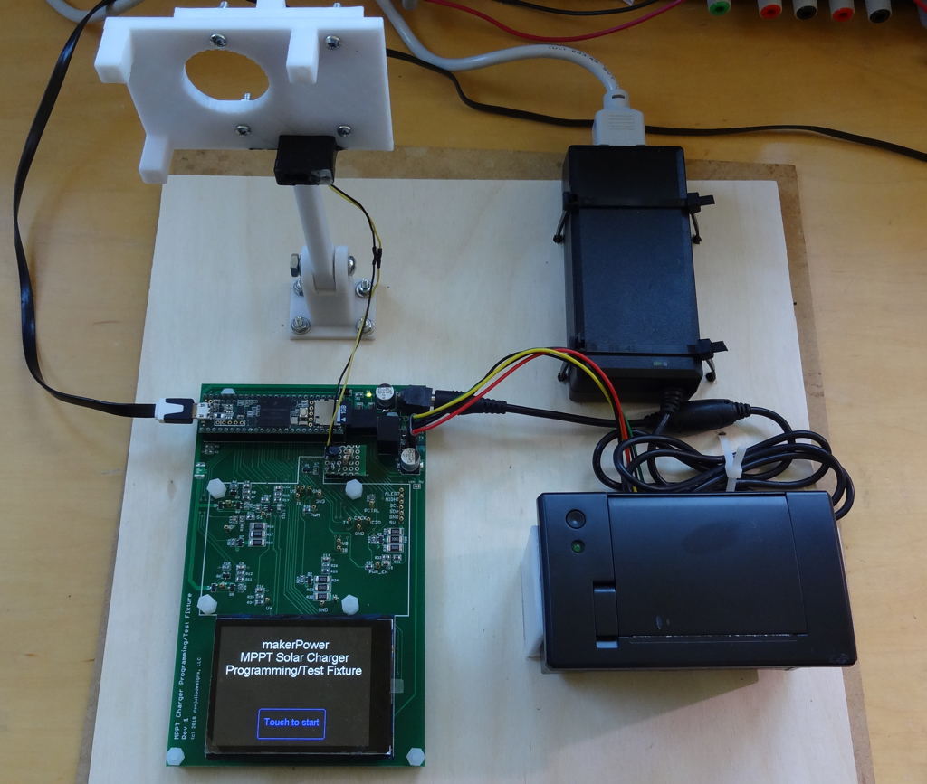
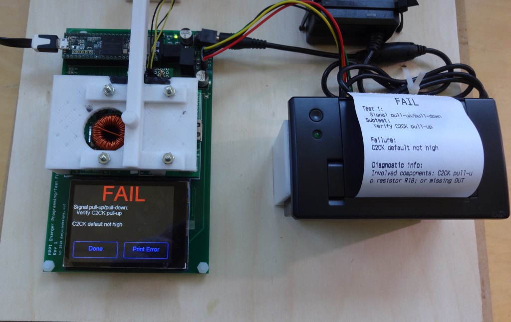
Coding was reasonably straight-forward and I 3D printed some components to make testing efficient (and to hold a photo-transistor for the charger LED verification). The big issue I had was the resistance of solder flux. These boards were hand-built by yours truly. I use a little flux to help reflow the SMT parts and this caused a lot of problems. I clean my boards using pure isopropyl alcohol and/or a quick soapy wash using a soft toothbrush, rinse and dry. However I still had problems making the two test fixture accurately measure voltages from the device-under-test (DUT).
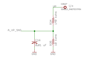
The test fixture measures voltages using the Teensy 3.5's ADC and an external precision 1.25 V reference. Higher voltages from the DUT are scaled using a voltage divider made up of two precision resistors. These resistors had to be fairly high resistance to not impact the circuitry under test.
Unfortunately flux under the resistors and between the soldered headers on the teensy and testfixture added measurable resistance and threw the resistance ratio off. The boards looked clean to me but still didn't measure correctly. It took a while before I found every source of error and managed to clean it up.
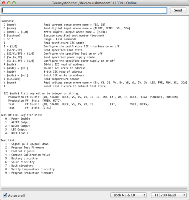
The test fixture also sports a simple command interface to enable manual control of the test fixture or running of individual tests. The command interface is not used during normal operation (no computer is connected to the test fixture).
Discussions
Become a Hackaday.io Member
Create an account to leave a comment. Already have an account? Log In.