 MCenderdragon
The main goals of this project are:
- keep the plant alive
- use as little power as possible
- notify me via internet if power/water runs low
- log temp, humidity, soil resistence
- one charge should last atleast 28 days
Currently I use an ESP8266 and programm it with Arduino. The whole thing should run on battery power.
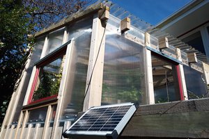
Maybe if everything works I will try to add a solar panerl for battery recharging.


 Sam Griffen
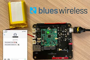
 Rob Lauer
 Dan Maloney
I really like where you are going with this. Do you have a better circuit diagram I could look at?