As I discussed in the previous log I've decided to modify the build to fit the speaker below the PCB, instead of gluing it to the lid of the Altoids tin.
The first thing to do was to determine how much vertical clearance inside the tin I had to work with. The two tallest components on the PCB are the 7-segment display and the battery. To measure how much I could elevate the PCB i stuck pieces of blu-tack on top of those components and squeezed the lid shut. I then measured the squeezed blu-tack pieces with a caliper. The display had a 5.5 mm clearance. The battery clearance was about 4 mm.
The PCB rests on top of a 3D-printed inner case, which at that point had a 1 mm thick "floor". So if I could make the battery the same height as the display there would be room for a 6.5 mm tall floor compartment for the speaker.
Battery holder
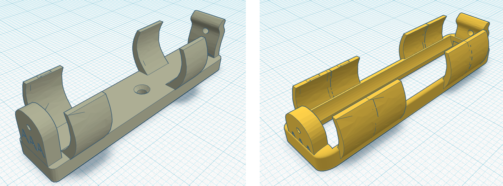
For my previous builds I've been using the excellent "flexing battery holder" model by Thingiverse user [enif]. Since it's a quite sturdy design I thought I could probably get away with shaving 1.5 mm off the bottom, which would make it the same height as the display.
But it turned out Tinkercad broke the model when I imported it—the integrated spring would print as two separate pieces. I have once in the past stumbled through the confusing process of fixing a broken model in FreeCAD, but I didn't want to put myself through learning all that stuff again.
Instead I found this battery holder by Thingiverse user [Morpheus0010]. It was the same height as the other one, but it did import properly into Tinkercad. I subtracted the base of the model which lowered it by about 2 mm. To hold the remaining pieces together I added some material around the bottom perimeter of the model. Now the battery would rest flush against the PCB. Since my printer isn't particularly reliable at printing thin details, I widened the "wings" of the model to make them less prone to breaking off. Here's the before and after:
Inner case:
The new inner case has a 6.5 mm tall compartment in its base to fit the speaker inside of. But you probably don't want to put a speaker that's thicker that 6 mm in there. It's wide enough to fit a 50 mm speaker, but most speakers of that diameter will probably be too thick. There should be plenty of smaller diameter speakers that fits though.
To save on material, I only left a small threshold around the edges for the PCB to rest on.
Another change I made was to lengthen the ridges on the sides that holds the PCB in place. I've had some problems before with the PCB sometimes getting loose.
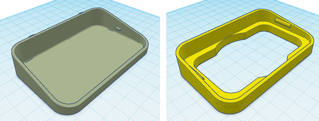
Note: The model is based on this design by Thingiverse user [mussy].
The next step
I'm feeling quite optimistic about this design. I'll need to make some minor changes to the PCB layout to accommodate for the new speaker placement. I'll check back when I've built and tried out the prototype.
Discussions
Become a Hackaday.io Member
Create an account to leave a comment. Already have an account? Log In.