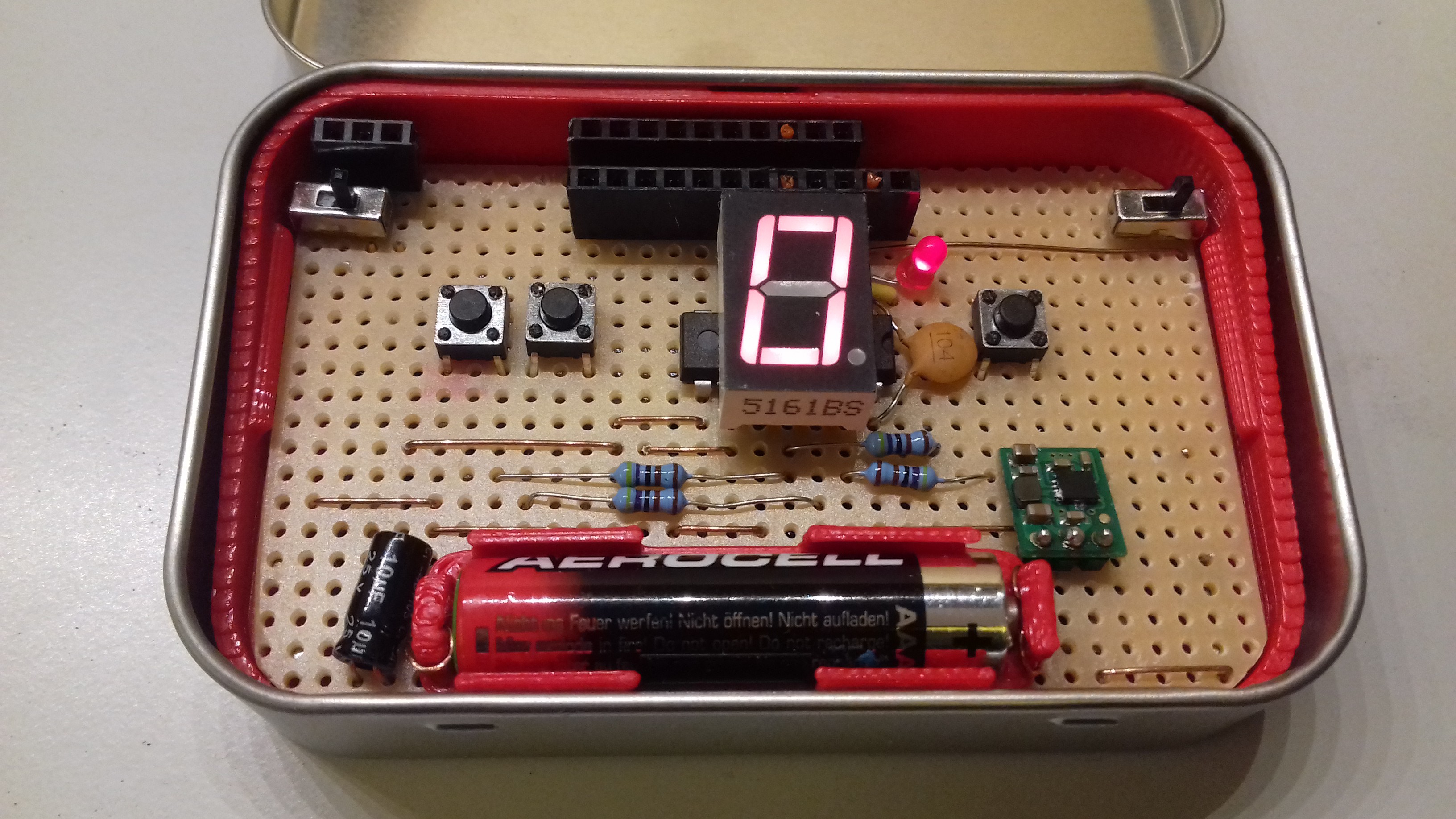
I've now made the "final" prototype for FATCAT. Of course there could always be some changes in the future, but they will probably be very minor in that case.
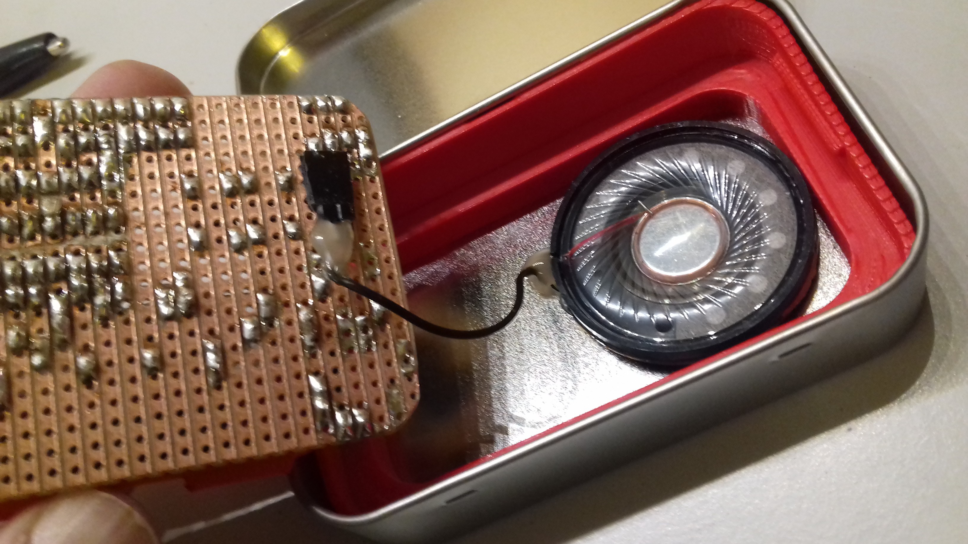
As discussed previously the major change with this build is that I've hidden the speaker below the PCB. I also added an extra pin header (top left) for connecting to external speakers or headphones:
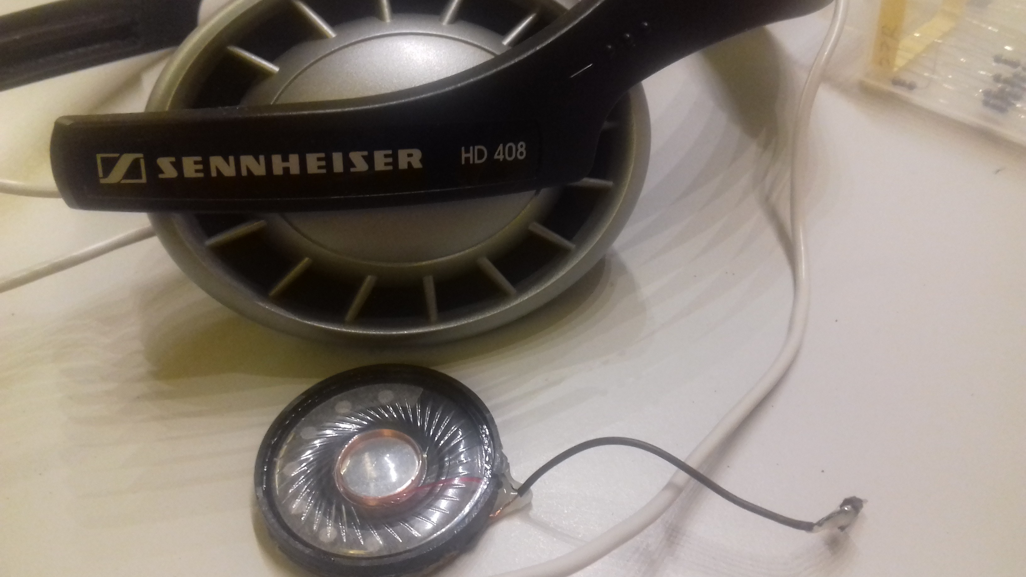
To get a speaker element of a suitable size I sacrificed a pair of old Sennheiser headphones:
I found that It's not really necessary to use any adhesive to fix the speaker to the tin, since its magnet itself is strong enough to hold it in place.
Using the original configuration, with dual inverted OCR pins for audio output, this speaker pulled quite a bit more than 40 mA out of each pin. One option would be to use a resistor to limit the current but that would be a bit wasteful. Instead I connected only one of the OCR outputs to the speaker, and tied the other speaker terminal to ground. With that configuration the speaker pulled about 38 mA, which should be fine. However dual outputs will still be useful for certain speaker elements, and especially for piezo speakers, which generally seems to draw less power.
I found that battery efficiency is a bit of an issue: When the battery is down to about 1.2 V the MCU brownout detection kicks in and resets the MCU whenever audio output is activated. I can't disable the brownout detection, since it's necessary to avoid EEPROM corruption.
In this build I tried using the Pololu U1V10F5 boost regulator, hoping it could pull a bit more power out of the battery. But the result was pretty much the same as with the no-name brand I had used before. Using two AAA cells in series would've been a better solution, but that simply won't fit on the PCB.
As a small measure to reduce idle power consumption I've replaced the discrete LED (originally green) with a red one, which in turn allows me to replace the two 2k2 resistors connecting to MCU pin 11 with 4k7 ones.
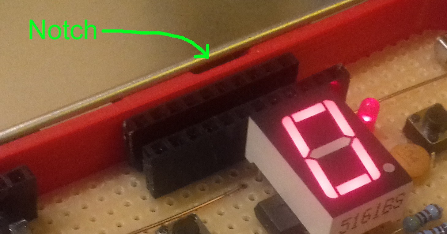
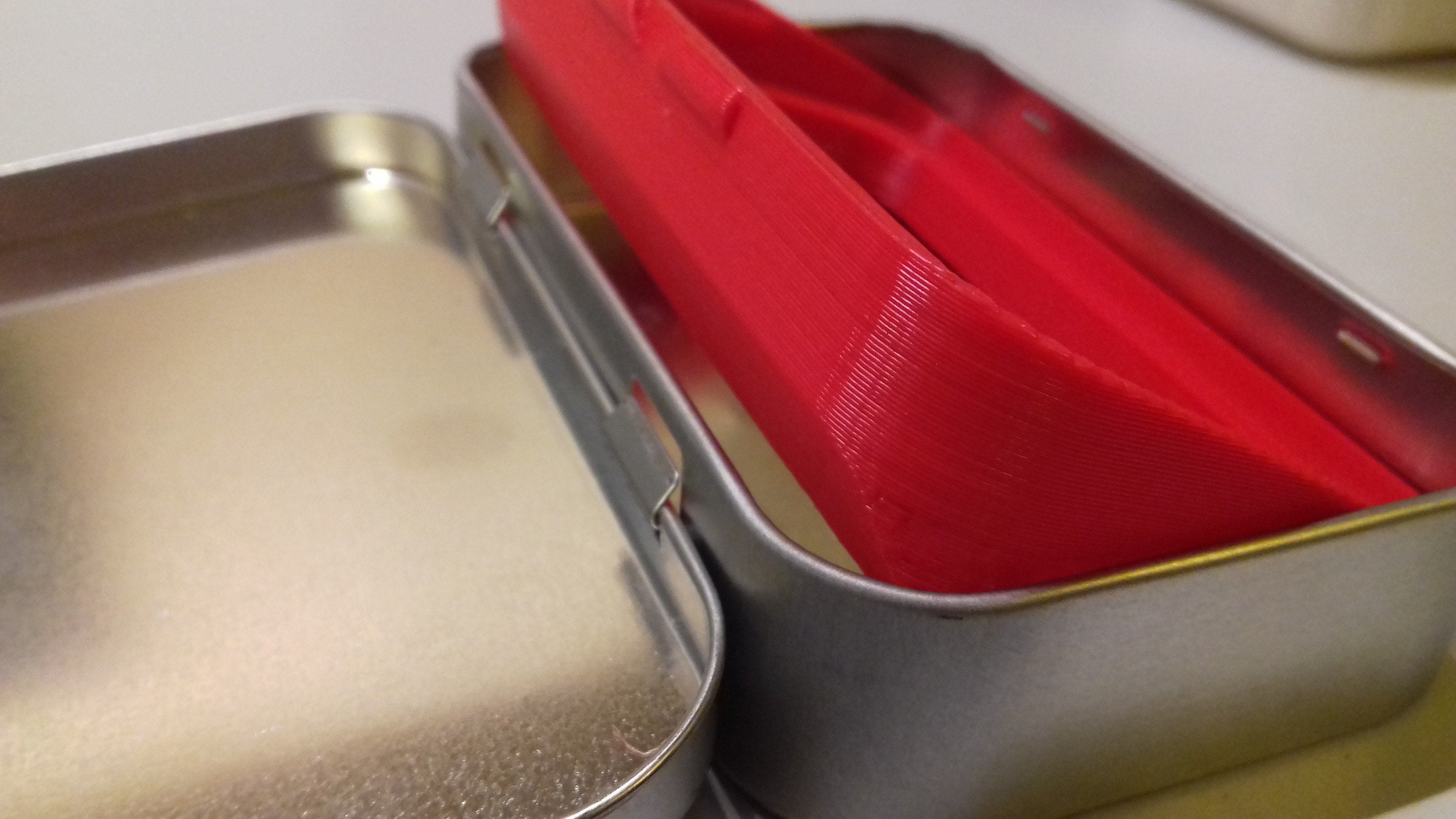
I had added a small notch to the PCB holder 3D-model, to make it easier to pry it back out of the Altoids tin if necessary. But I found that the action of prying it out could damage the battery holder, since it would get pinched between the PCB and the inside of the tin. To remedy this problem I added a gradual cutoff to the base of the PCB holder, in order to give it more room to slide out without getting caught on anything.
Discussions
Become a Hackaday.io Member
Create an account to leave a comment. Already have an account? Log In.