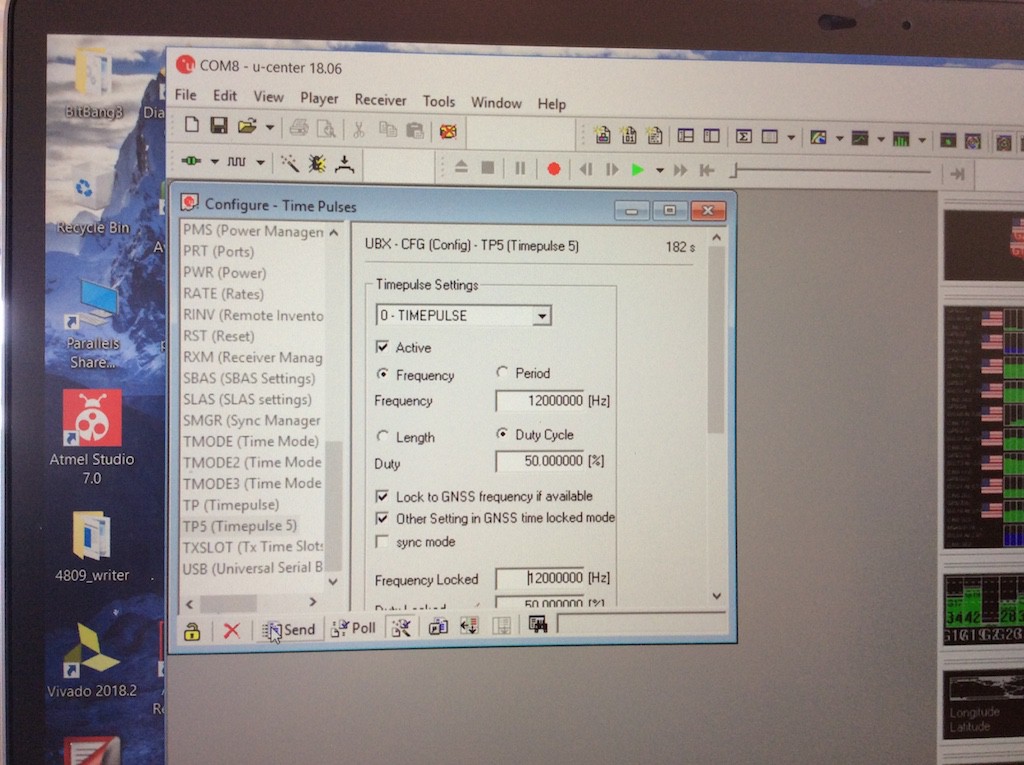
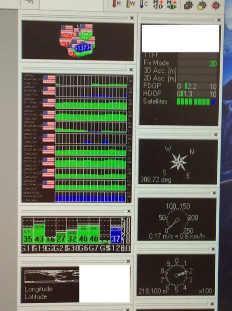
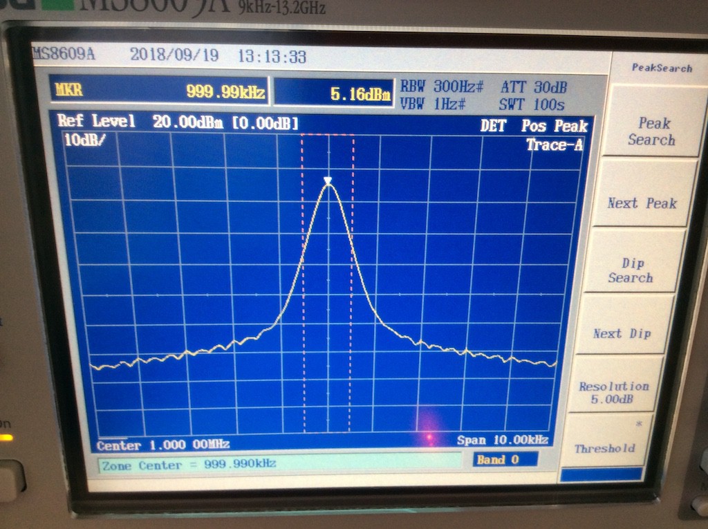
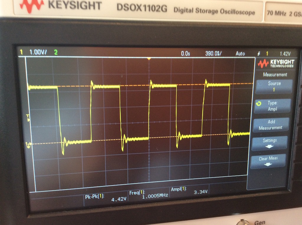
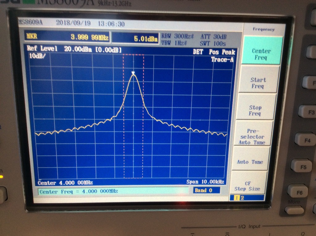
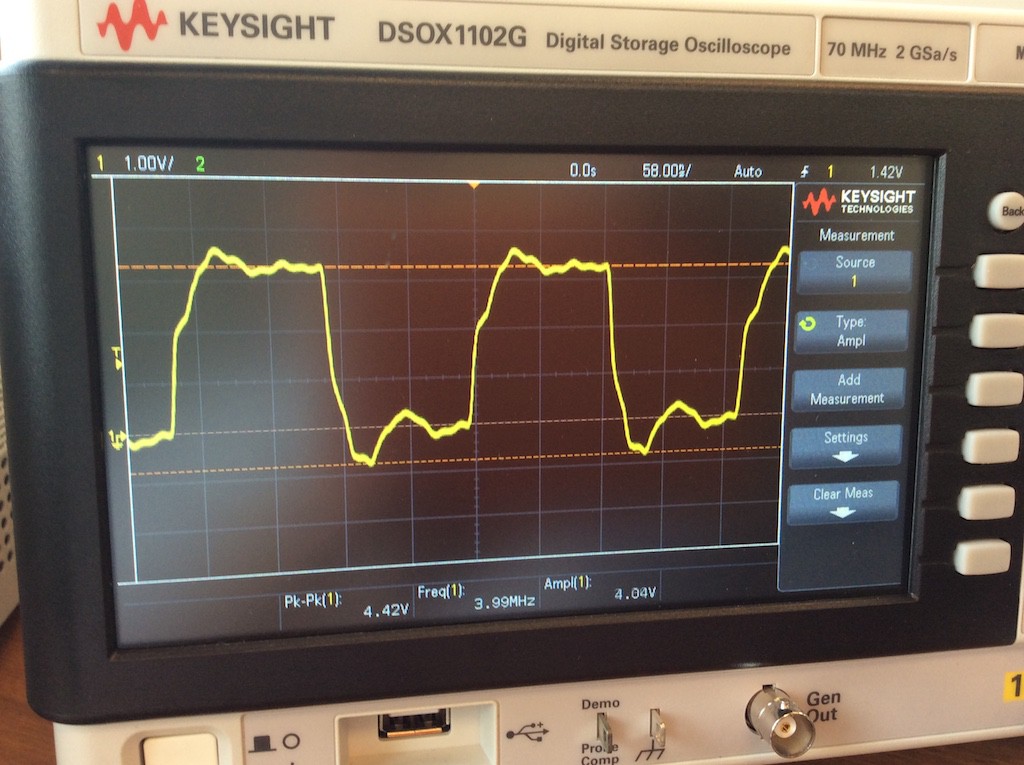
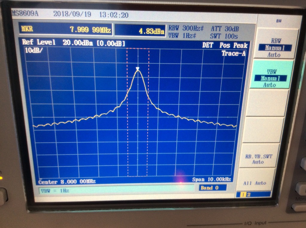
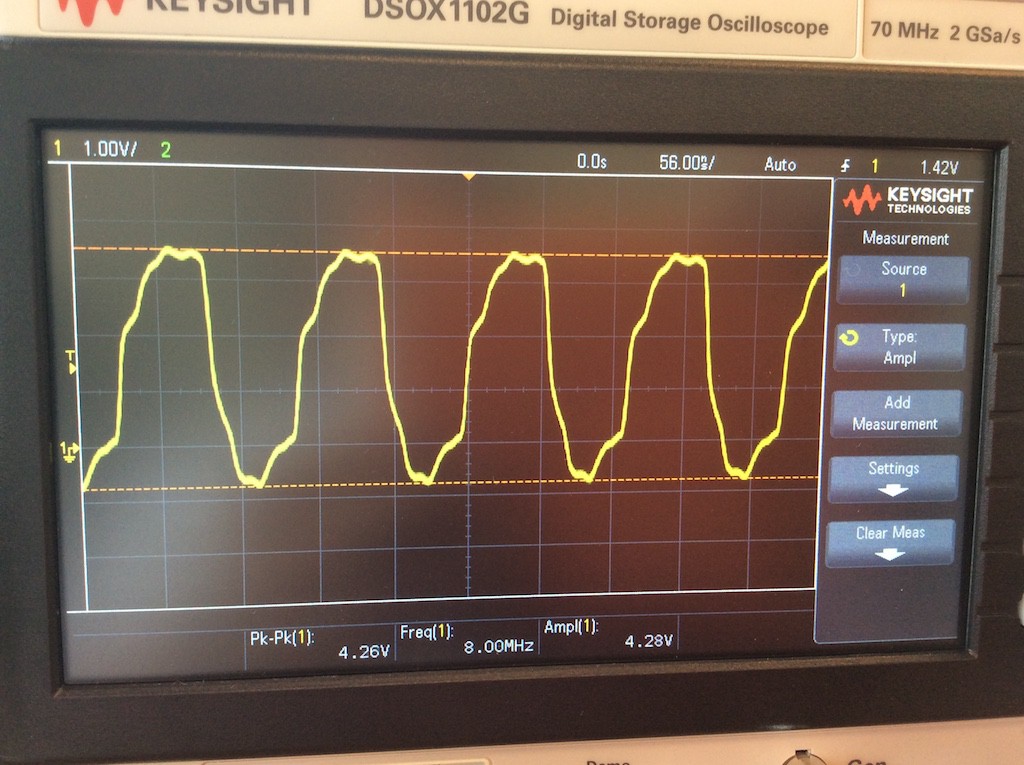
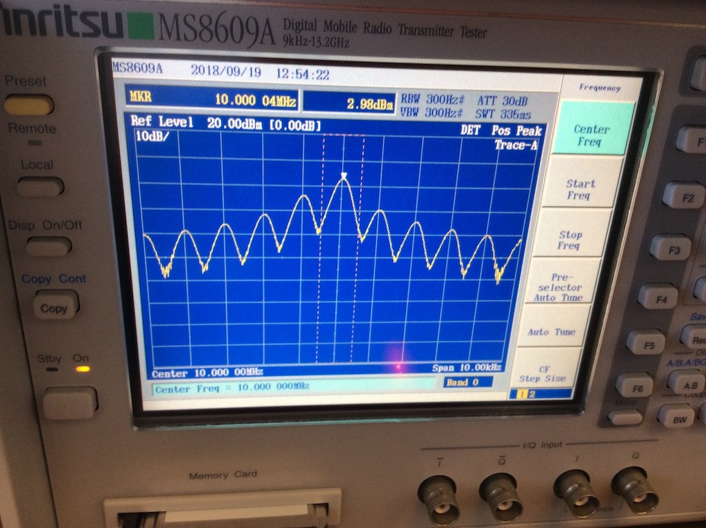
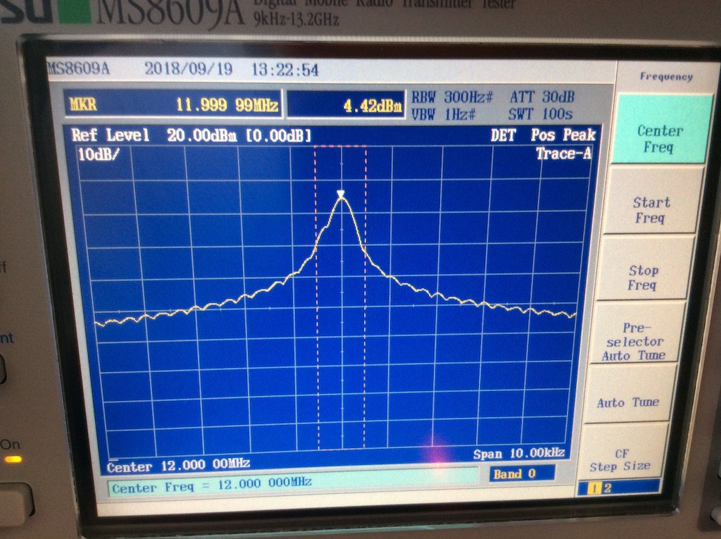
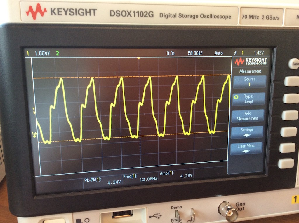
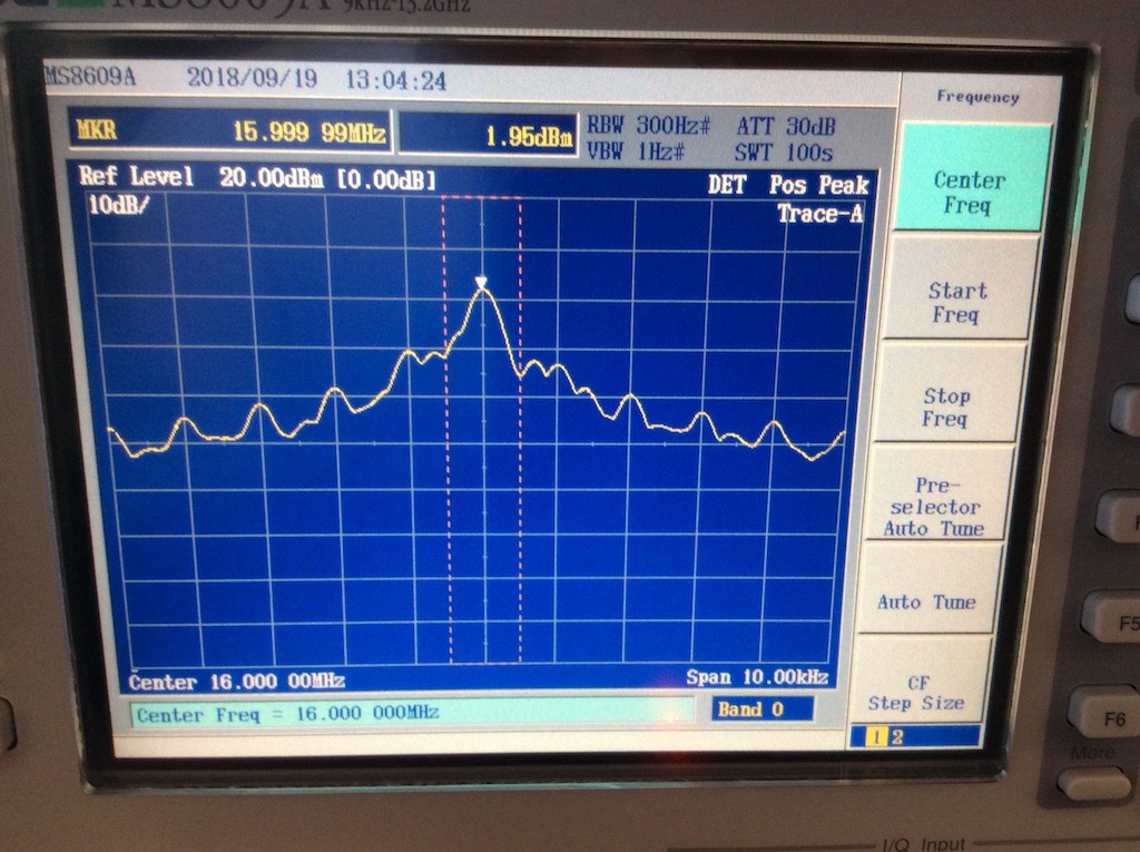
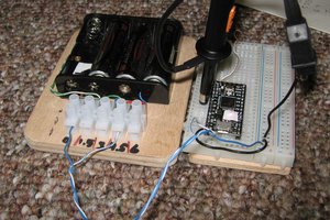
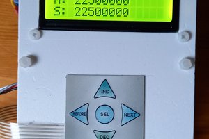
• Evaluating phase noise..

    kodera2t10/27/2018 at 09:58 0 comments

    Actually this is the first time for me to measure "phase noise" (my main field is passive component, and not oscillator field) but I found most of spectrum analyzer can measure and calculate dBc/Hz value by the embedded function.

    Here I will simply show the result below. Each evaluation is done by 100 and 300Hz RBW with 10kHz offset value. The first ones are 10MHz output.

    As you see, it is around -74.5 dBc/Hz. 

    Next one is 20MHz case,

    The value for 20MHz is around -70dBc/Hz.

    The last ones are the case of 200MHz (maximum frequency of Si5356).

    The floor is buried in the noise level and I may need change ATT value but tentatively it is around -65dBc/Hz.

  • How to configure output frequency of Si5356?

    kodera2t10/17/2018 at 01:34 0 comments

    Si5356 is quite useful one chip PLL IC with four output. Each output can have different and arbitral frequency and they can be configured through register setting inside Si5356. The details are described in the application note 

    https://www.silabs.com/documents/public/application-notes/AN565.pdf

    but direct setting and calculation is not easy one. But Silicon Lab releases a very useful software named "Clock Builder Pro" at

    https://www.silabs.com/products/development-tools/software/clockbuilder-pro-software

    Just installing the software above and writing the configuration will generate register values for Si5356.

    Click "Create New Project" and,

    select "clock generators" and

    select the device name "Si5356" and push "Next" and,,

    then configuration window will appear. Here the clock source pin IN4 and set 8 MHz and we can write any frequency for output 1 to 4 from 1 MHz to 200 MHz. Here is the example of 10, 20, 100 and 200 MHz. After writing values and push Next and

    Push "Export" and,,

    Select and select export file name for "C Code Header File" and you will get the register setting file named as "*.h".

    The generated file will contain the information as the above. The first digit (29 and 30) corresponds to the address of Si5356 and next data (like 0x20 and 0xA8) is the value to be written. The last one is the writing bit mask. 0xFF meaning full 8-bit can be re-write for register setting. The details are available at AN565 and please refer them.

  • How to setup pps setup for 8MHz in u-blox Neo6M?

    kodera2t10/17/2018 at 01:09 0 comments

    Originally u-blox Neo6M will produce 1 Hz pulse for pps output but it can be configured for another frequency even 8 MHz. This is the procedure how to set it to 8MHz. This setup is useful also for the case if my board (frequency counter or frequency standard) lost its configuration.

    After installing u-blox's configuration software, which can be available at

    https://www.u-blox.com/en/product/u-center

    , just connect your UART to the computer, and your computer will recognize COM port and connect it with UART and computer.

    After installing, open "Configuration View" in View and you will see,

    The setting window in TP5 register. Here you can write 8MHz 50% duty cycle (or another frequency and duty cycle).

    Just writing the value is not enough to configure but push "Send" button below will activate your new setting.

    In addition, the new setting can be saved in the module and onboard SPI flash. Select the device and push "Send" button at the bottom of window will save the new configuration and will reload after power off/on cycle.

  • Super high precision GPS trained frequency standard for 1 to 200 MHz.

    kodera2t10/05/2018 at 13:01 0 comments

    This is most practical item I've ever made!!!!

    Now I made another version. This board can generate arbitral frequency signal from 1 MHz to 200 MHz with Silicon Labs Si5356 with GPS trained 8 MHz clock. Si5356 can be programmed (I2C command can be published) from ATmega88A (indeed, 328 is too much for this job) and 4-outputs can have different frequency.

    Indeed any time domain related "precision conscious" measurement instrument has "10 MHz IN" terminal. They are the standard clock input and connecting this board setting 10 MHz to such an instrument will provide "atomic clock precision" in time domain measurement. Not only connecting measurement instrument, just for the purpose of high precision frequency standard for any frequency up to 200 MHz, this board will be quite useful.

    The I2C command publishing by ATmega88A is done through, actually, Arduino sketch. Si5356 requires lots, bunch, many register setting containing input signal source frequency, output signal and lots of property but we can send them step by step as is written by Arduino sketch..

    Actual operation can be found in the following movie. Please note that, 40 MHz waveform is not "real" one due to lack of oscilloscope BW (it is just 40 MHz). Already I've confirmed its "real" waveform by more wider BW oscilloscope and it was more "square-wave form" than in this movie.

    Again, this is the most practical item I've ever made. Any 70's 80's 90's time domain related instrument (VNA, SPA, oscilloscope, SG) with 10 MHz input will get the atomic clock precision from GPS by ultra low cost!

    If this appears on my tindie store, it will be less than $50...

  • And now it is available at tindie!

    kodera2t09/23/2018 at 23:21 0 comments

    Eventually the item is release on my tindie store. Please visit if you have interest!!!

    Super high-precision GPS trained frequency counter

  • Now it's done!

    kodera2t09/22/2018 at 02:22 3 comments

    Now it's done in single board form! Two SMA connectors are GPS antenna and frequency counter input, connecting to PD5 of ATmega328 through single gate inverter element. Rotary encoder change gate time for frequency measurement. Coin battery (CR1220) keeps setting of NEO6M (8MHz clock generation..). The RED toggle switch can select the connection between CP2102N to NEO6M or ATmega328, which enables GPS monitor or Arduino sketch upload through USB. As same as most of my board, onboard Lipo battery charger is prepared. The Yellow toggle switch change the clock source of ATmega328, on-board 8MHz crystal or GPS trained signal. Actually NEO6M generate 8MHz even before GPS locking (with low precision) and after GPS clock capturing, it goes to atomic clock precision!. 

    Here is the measuring result of a clock (1 MHz) generated from another GPS module. As you see it surely measuring.. Yes, it's battery operation!!

  • Making high precision frequency counter by GPS trained clock

    kodera2t09/21/2018 at 08:47 0 comments

    Here just jumping to the result, but I've succeeded to make the frequency counter, driven by GPS trained clock (8MHz). The original 8MHz Arduino (Arduino Pro/mini) utilizes internal RC 8MHz oscillator and I re-write fuze bit for crystal oscillator. The reason why not "external clock source" but "crystal oscillator" is for switch-ability bbetween internal crystal clock operation and GPS clock. Just disconnect X1 terminal of crystal and injecting GPS single instead, AVR works under GPS clock.

    For frequency counter implementation, I utilized a library at

    http://interface.khm.de/index.php/lab/interfaces-advanced/arduino-frequency-counter-library/

    Just we need to change pre-scaler of register for 8MHz clock operation, as

    In addition, I added rotary encoder for gate timing switch and OLED display as shown in the above image. Indeed the image shows the measurement of 1MHz generated by another GPS module. Independent two GPS module has encounter the same result ! (I am not sure if GPS is not accurate, but I guess we can believe.)

  • Measurement spectrum and time domain waveform of "TP5" of u-blox Neo6

    kodera2t09/21/2018 at 08:29 0 comments

    u-blox, the company selling GPS module, indeed less than $10, releases a utility application named "u-center" and through its application we can configure output frequency of "PPS" terminal up to 10 MHz.

    During the GPS status like above (getting enough information for positioning, but I don't use position information), time domain and spectrum are measured for several frequency range.

    The first one is 1 MHz spectrum. Please note it is 10 kHz span (one horizontal division is 1 kHz). VERY CLEAN!

    Accordingly, time time domain waveform is also clean, naturally.

    Let's try 4MHz. YES it is still clean!

    Yeah, it is clean pulse. Please note that, the connection is not 50 Ohm line but just breadboard jumper and we may get more clear signal with shielded and impedance controlled situation.

    This is 8MHz, still clean, very clean. We can drive ATmega328 with Arduino bootloader with this signal now.

    Yes, it has a clean manner! Enough clean to drive MCU!

    Now let's try 10MHz. Indeed 10 MHz is a commercial standard signal (any time domain related measurement instrument has 10 MHz in/out.), and if we can easily get 10 MHz, it should be quite useful,, but as you see, surely 10 MHz is the maximum spectrum frequency but it is not pure one at all. In the datasheet of u-blox Neo6, this "bad spectrum" is due to the way to generate signal. The original frequency is 48 MHz and the signal is generated by internal "bad" PLL. It seems, the frequency divided by integer seems clear spectrum and waveform...

    The result of 12 MHz. The spectrum again get very clean. Yes, 12=48/4.

    As noted above, if we use impedance controlled careful signal line from GPS module to oscilloscope it may have more clear waveform...

    Now let's try 16MHz. 16 is 48/3 but not so clear (but clear than 10MHz case).

    It has a glitch in time domain waveform. Through appropriate filter we may use this for MCU clock but this time I will use 8 MHz signal for MCU driving. (Indeed this is out of spec in the datasheet).

  • The beginning: Why do I need frequency standard?

    kodera2t09/21/2018 at 08:10 0 comments

    Recently, I got a "programmable cystal oscillator module" which can generate arbitral frequency signal from 1 MHz to 125 MHz. The output is generated by internal PLL, and it is commercial item and I think (believe) the accuracy is reliable and we will get any frequency with high accuracy. 

    The above picture shows the measurement result of a clock module programmed as "3.1416 MHz". For hobby (and most of digital application) , these 5-digit accuracy

    is enough but I don't have any confidence more than five digit. What happens less than more? In order to get what is the exact frequency of oscillation, we definitely need high precision frequency counter (or spectrum analyzer or else) driven by high precision frequency standard like rubidium oscillator. Even rubidium is not versatile due to its "aging". Periodic calibration is required to keep it and the price is not "inexpensive". Of course if you are involved in "national project", you can order and ask annual calibration but, at least, this is personal interest and I cannot pay hundreds dollars for it.. 

    Indeed I was almost buying rubidium at eBay but actually really good news I found! u-blox's GPS module datasheet says it can generate arbitral frequency signal up to 10 MHz, which is SYNCHRONIZED to GPS time!!!!!!

    Of course drives me to make high precision frequency counter trained by GPS signal!! Yeah!