 Kelly Heaton
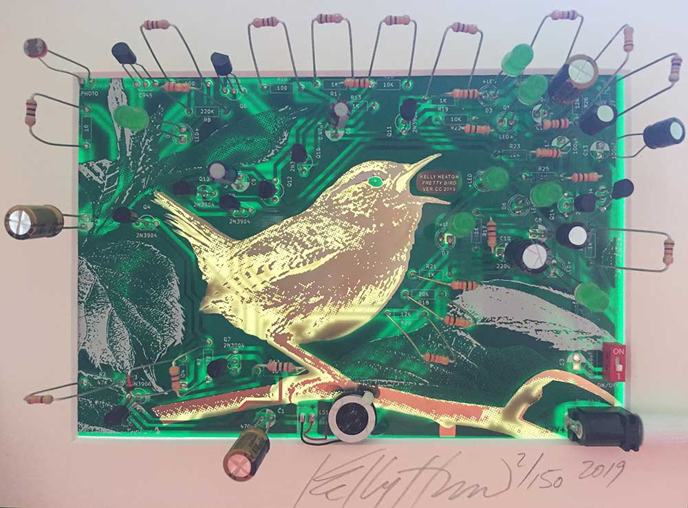
Pretty Bird ver. CC (2019) is an edition of 150 artistic printed circuit boards and associated parts that was commissioned by Creative Capital for their 20th anniversary retreat celebration. Creative Capital covered the cost of materials and I donated my time to realize the project. The printed circuit boards were manufactured by PCBWay in Shenzhen, China according to my specifications.
The functional circuit design is based on my effort to electrically generate the “pretty bird” song made by a Carolina wren using simple, low-cost, and discrete hardware. The electronic behaviors (blinking lights, chirping bird) are caused by analog oscillations, which is to say, the waveforms are entirely generated by the discrete hardware and circuit traces that visibly surround the bird. No hidden software or recordings are involved. I would like to thank @DJ Mystic for providing me with a negistor oscillator circuit that I adapted for part of what you see here. I have uploaded my schematic and hope it will inspire the work of others in the Hackaday community.
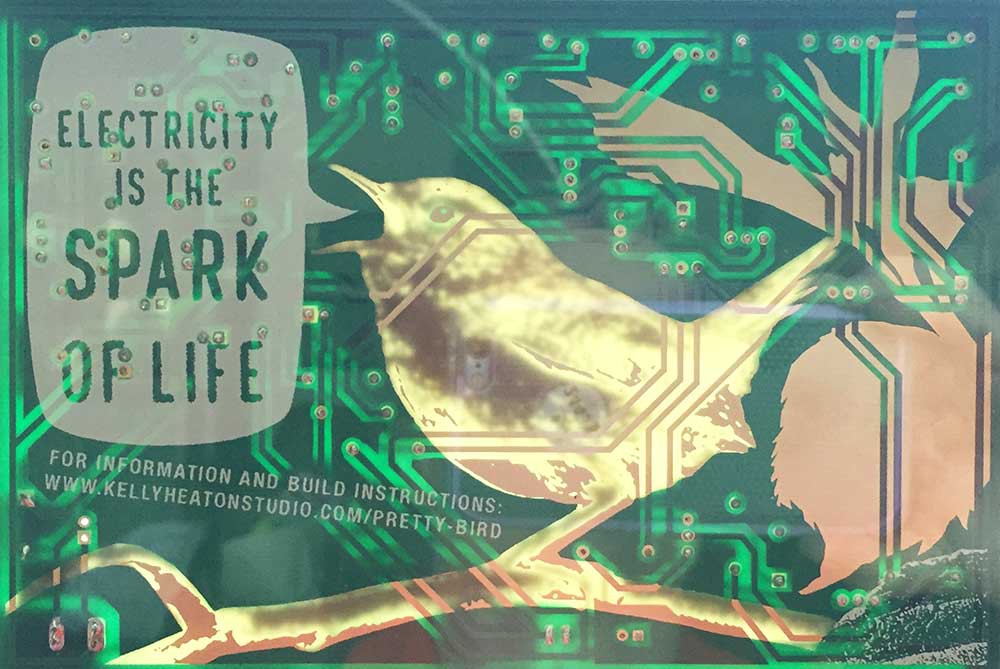
The central visual element of the board is a bird etched in exposed copper that has been electroplated with gold. The wren sits in a green and white forest defined by leaves and circuit traces. When the components are added, this forest effect is enhanced by the physical depth and texture that they create surrounding the bird. As you can see, I like to leave the component leads long because it makes the circuit appear "wild" and oddly natural. If you hold the circuit board up to a light, there is a watermark effect thanks to the translucency of the raw FR4 board substrate (versus the opacity of surrounding copper and solder mask).
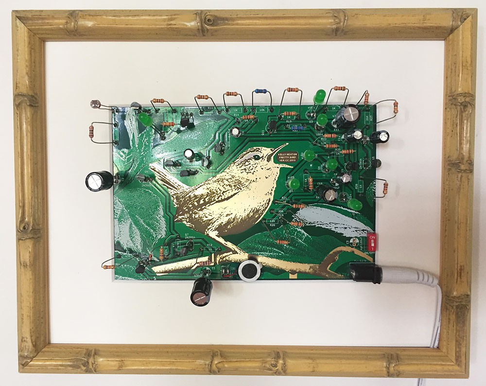
This work of art —a multiple— is complete regardless of whether the owner elects to assemble it, although soldering and electrifying the circuit manifests additional dimensions of the piece as shown in my video. The piece is designed to be framed and displayed dead or alive, with or without the components installed. Unlike many engineers, I accept that my circuits will eventually die from wear and tear because death is part of life -- and circuits are indeed alive in their own way.
As for framing, I used no glass on the front, but glass for the frame backer so you can see both sides of the circuit as well as the watermark. Bamboo is my frame of choice for this piece as it enhances the naturalist aesthetic and hints at the board's place of manufacture.
HOW TO ASSEMBLE THE CIRCUIT
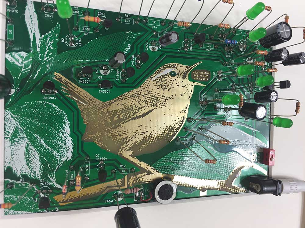
Pretty Bird CC (2019) comes with the following electronic components (board reference in parentheses):
Quantity 1: 0.47 uF electrolytic capacitor (C6)
Quantity 4: 100 uF electrolytic capacitor (C8, C12, C13) *C3 is unused - leave empty
Quantity 1: 220 uF electrolytic capacitor (C10)
Quantity 1: 47 uF electrolytic capacitor (C9)
Quantity 3: 470 uF electrolytic capacitor (C1, C2, C11)
Quantity 1: 1N4148 general purpose signal diode (D4)
Quantity 7: Green light emitting diode aka “LED” (D1, D2, D3, D6, D7, D8, D9)
Quantity 1: 2x5.5MM power jack (J1)
Quantity 1: 8 ohm speaker (LS1)
Quantity 8: 2N3904 NPN transistor (Q4, Q7, Q9, Q11, Q12, Q13, Q14, Q15)
Quantity 2: 2N3906 PNP transistor (Q3, Q10)
Quantity 2: KSC945Y NPN transistor (Q2, Q6)
Quantity 2: 10 ohm resistor (R1, R12)
Quantity 2: 100 ohm resistor (R4, R10)
Quantity 3: 12K ohm resistor (R20, R23, R26)
Quantity 2: 10K ohm resistor (R16, R22)
Quantity 8: 1K ohm resistor ((R13, R14, R17, R19, R21, R24, R25, R28)
Quantity 2: 20K ohm resistor (R18, R27)
Quantity 1: 220K ohm resistor (R8)
Quantity 1: 470 ohm resistor (R7)
Quantity 1: 47K ohm resistor (R2)
Quantity 1: Light-dependent resistor (R3)
Quantity 1: On/off slide switch (SW1)
Quantity 1: 12 volt DC power supply with minimum 300 mA
Extras: I made two small edits to the circuit after the boards were manufactured. These changes are not essential, but they do give a nicer chirp quality in my opinion. Scroll to the end of this page for info.
NOTES ON THE ASSEMBLED AND ELECTRIFIED BOARD
When the red power switch is in the “off” position, the green LED lights will blink in a pattern that is generated by a series of analog electronic oscillators. When the switch is flipped to the “on” position, you hear sounds associated with these same oscillations —reminiscent of a chirping bird. In the upper left corner of the circuit board, there is a light-dependent resistor that affects the frequency of oscillations. If you get the lighting conditions are favorable, the circuit will make a sound that is reminiscent of a Carolina wren’s “pretty bird” song.
TWO HACKS:
Solder an additional 1K resistor in parallel with the resistor at position R19, and
solder an additional 20K resistor in parallel with the resistor at position R23
(If you must know why: the LEDs that I used during prototyping drew more current than the LEDs that I used in the final board assembly. These hacks compensate for the change.)
Among other reasons, I am publishing this project to Hackaday because I wonder whether a circuit like this would make an interesting product (as a kit) if I re-engineered it to run on a 9V battery? Although fine art is my primary occupation, I am not above adapting certain works for a mass audience if there is sufficient interest and opportunity. I think these "circuit birds" could be a great educational experience for people wanting to learn analog electronics, or to explore the similarities (simulacrum?) between biological organisms and machines. I mention this because I have numerous other bird circuit designs that could be adapted for a similar "kit" format.
Your feedback is appreciated!
Discussions
Become a Hackaday.io Member
Create an account to leave a comment. Already have an account? Log In.