Close
0%
0%

CP/M 50 Mk II

Fast, small, available. Pick any three.

Similar projects worth following
A one square inch 50MHz Z80-compatible CP/M computer built from stocked parts. Like its predecessor, the Mk II is based on the Zilog eZ80L92 microprocessor. Leveraging the L92's native interfaces and careful part selection packs a great deal of functionality into a small footprint.

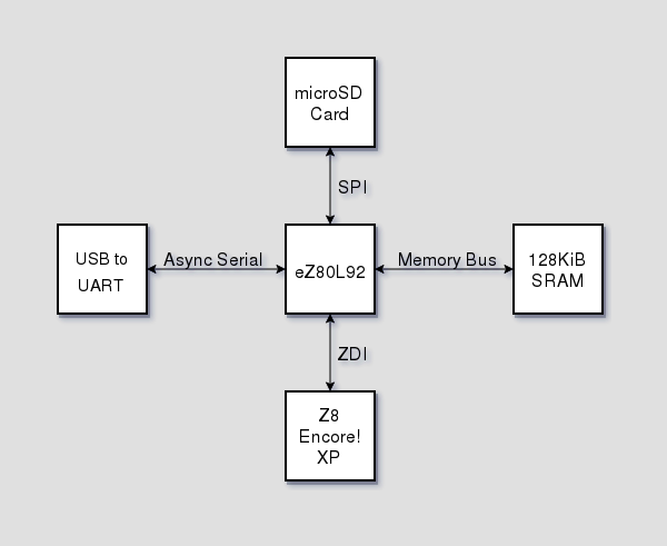
The design is built around a ZiLOG eZ80L92 Z80-compatible microprocessor.  System memory is provided by a 128KiB SRAM. Disk storage is provided by a microSD card connected to the L92's SPI bus.  A USB to Dual UART bridge provides connectivity for a serial console.  A ZiLOG Z8 Encore! XP microcontroller bootstraps the system using the L92's ZDI debug interface.  An LDO regulator powers the system from the USB bus.  Below is a block diagram of the system.

The board runs CP/M 2.2 that consists of a custom BIOS and the standard CCP and BDOS modules.  The custom BIOS provides serial console and disk access using the L92's UART and SPI interfaces.

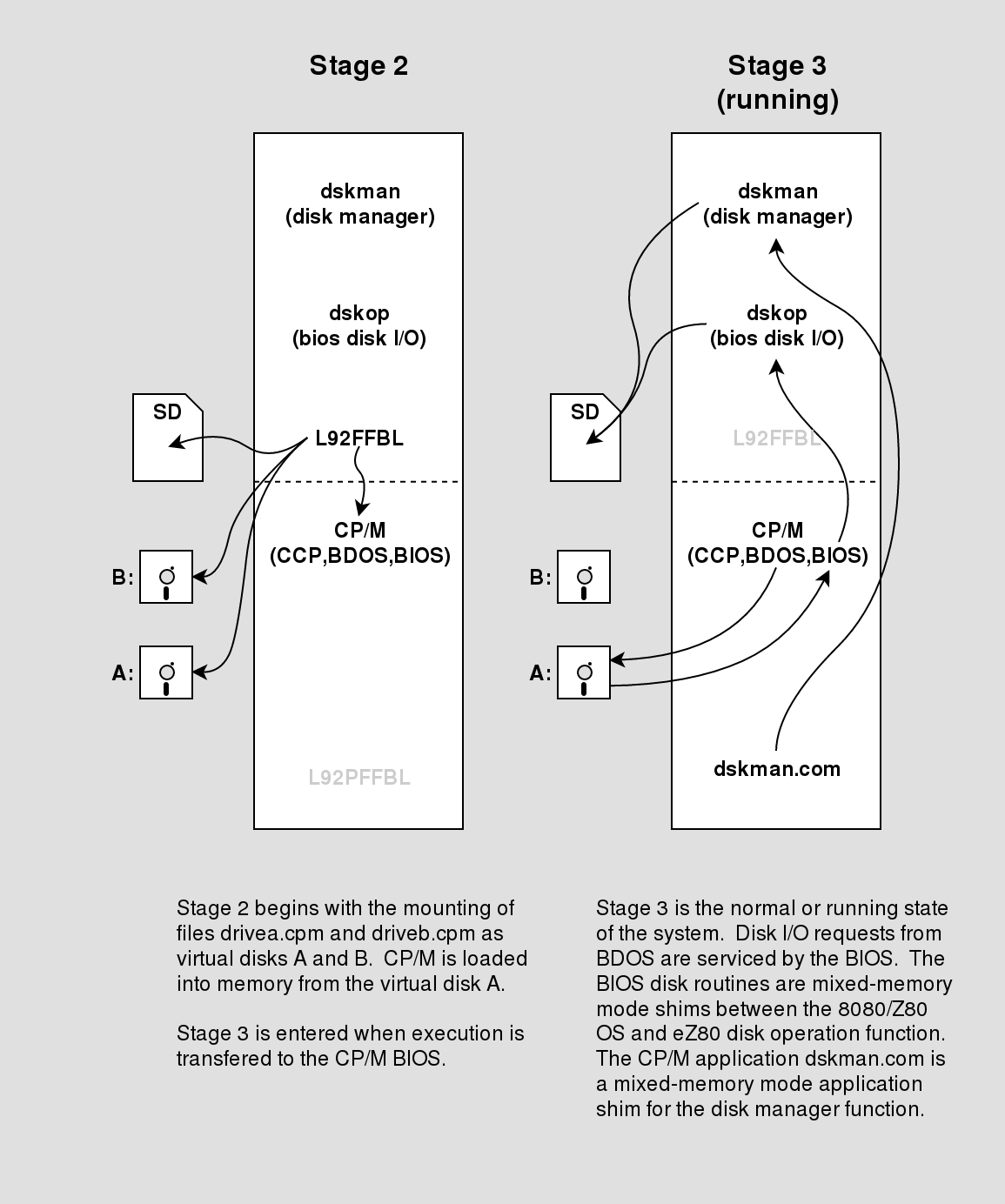
The default disk manager configuration emulates four 8" single density floppy disks and two 4MB hard disk.  Disk images on the microSD card are associated with a drive using the mount command, e.g. mount mbasic.dsk b.

Both the bootloader and disk manager access the microSD card in its native FAT format using the Petit FatFs and FatFs modules respectively.

Use of a microSD card and the FAT file system makes loading disk images as simple as copying files.  The choice of disk geometries matches many of the disk images provided for the z80pack development system.

This project would not have many of its features without projects like FatFs, z80pack and others.
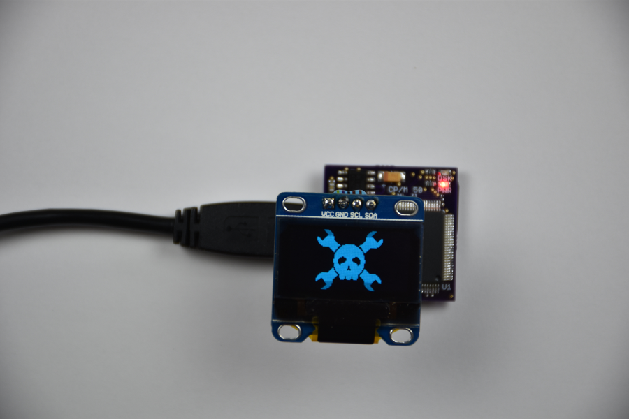
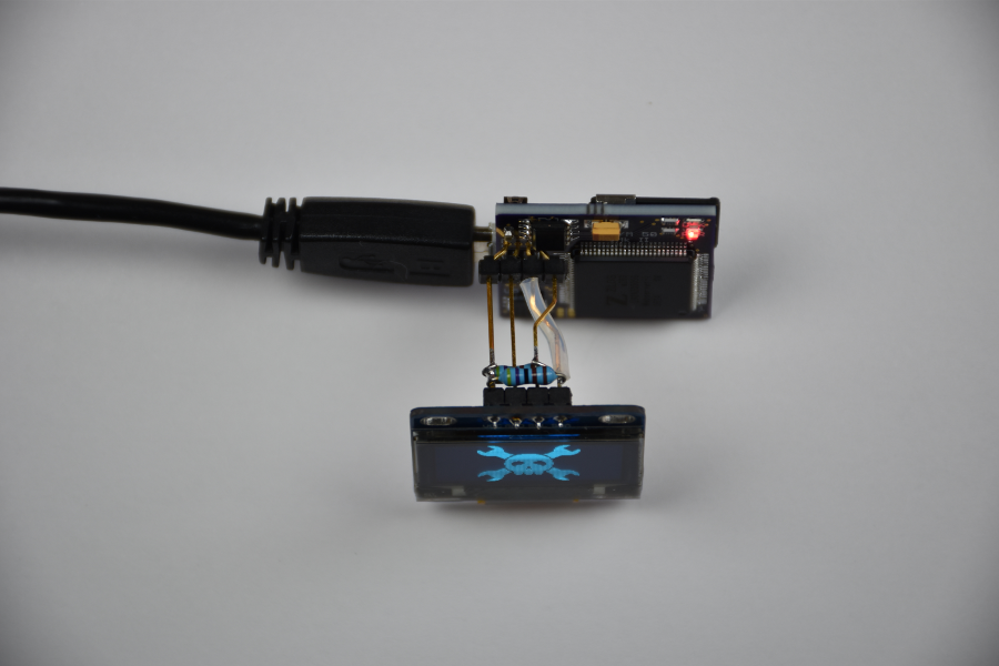
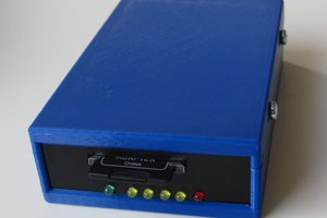
Blinkenlight

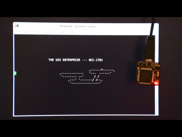
Here's a short video of the board in action.

Hardware done! Software source to follow available in links section.

Software Development Tools

The Zilog Developer Studio packages now appear to be gratis.

cpm50mk2-eagle-bom_rev-.txt

Parts list for revision -

plain - 2.89 kB - 07/29/2019 at 02:10

Download

cpm50mk2-gerbers.tgz

Gerber files

x-compressed-tar - 28.40 kB - 10/01/2018 at 04:02

Download

cpm50mk2-eagle.tgz

EAGLE PCB schematic and board files.

x-compressed-tar - 88.09 kB - 10/01/2018 at 04:00

Download

cpm50mk2.mov

QuickTime video showing board in action. 0:04 starting piccom, resetting board, directory listing of drive A 0:15 starting disk manager, list mounted disk images, mounting microsoft basic disk image 0:52 changing to drive B, running STARTREK on microsoft basic 1:22 changing to drive C, directory listing

quicktime - 13.96 MB - 10/01/2018 at 01:28

Download

Adobe Portable Document Format - 74.28 kB - 09/30/2018 at 01:57

Preview
Download

  • 1 × EZ80L92AZ050SG Zilog 50MHz Z80-Compatible Microprocessor
  • 1 × AS7C31024B-10TCN 10ns 128KiB Static RAM
  • 1 × BAT54 SCHOTTKY Diode
  • 2 × Red, LED Fiber Optics / Emitters
  • 11 × 10K Resistor Resistor

View all 17 components

  • Rev A Boards Out for Production

    jessexm10/21/2018 at 22:27 0 comments

    Revision A boards should be back in a week or so.  The first revision required a blue wire to correct an issue with reset and the addition of a resistor and capacitor.  The new revision fixes these issues and also simplifies repurposing the Z8 programming serial port.  New features include RTS/CTS connections for hardware flow control and connecting a previously unused Z8 pin to the L92 RTC clock.  The Z8 clock source is a trimmable internal  precision oscillator and the unused pin happened to be a timer output, so we'll see if the RTC proves to be useful.

    The new EDA files will be posted to the projects github repo; with the return of the square inch contest completed, congratulations to the winners, the current EDA files will be removed from the files section. 

    If you are contemplating building one of these boards I would wait for the new revision to be released; the rework is a bit fiddly.

  • Boot Process Diagrams

    jessexm10/15/2018 at 00:50 0 comments

    Here are a couple of diagrams of the boot process.

    1. at reset, push first bootloader into external RAM then reset eZ80 to start first bootloader
    2. first bootloader loads second bootloader/disk manager/disk operations binary from microSD
    3. second bootloader mounts virtual disks for drives A and B, loads CP/M from reserved tracks of drive A, jump to BIOS coldboot entry point
    4. CP/M running, virtual disk access provided by BIOS and mixed-memory mode disk I/O function

    The limited amount of flash in the Z8 drives the need for two bootloaders. The largest Flash for an 8-pin Z8 is 8KiB.  The desire to keep the µP and µC Zilog drives the Z8 and the board size drives 8-pins.

  • I2C expandability

    jessexm10/08/2018 at 19:35 0 comments

    The L92's I2C interface along with power and ground are available for external use.

    Here are a couple of action shots showing off the Hackaday logo on an I2C 128x64 OLED display.

    Here's the I2C pinout.

  • Software repos are up

    jessexm10/08/2018 at 04:03 0 comments

    Just added software repos to the projects links section.

View all 4 project logs

  • 1
    Programming the Bootloader

    Program the ZDI bootloader using the flash utility included with the dbgutils package that is part of the Z8 Encore Tools repo.

    ./flashutil -u -c 5330000  -p /dev/ttyUSB0 zdiloader.hex

    Where:

    • -u enables 8-pin device OCD Interface unlock sequence
    • -c sets the clock frequency during programming
    • -p specifies the first CP/M 50 Mk II serial port
    • zdiloader.hex is the firmware

View all instructions

Enjoy this project?

Share

Discussions

kriebe wrote 05/12/2023 at 13:46 point

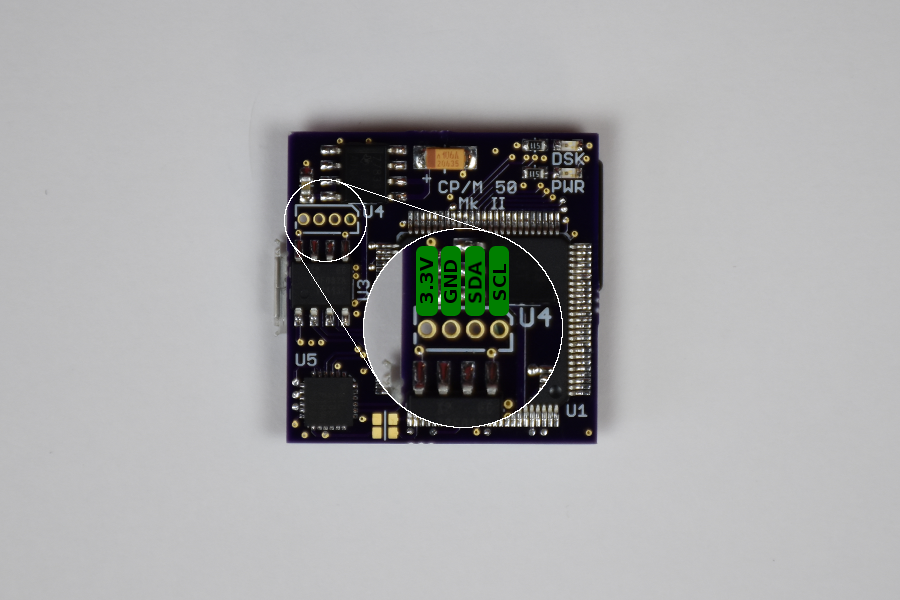
It is a pity that the project was not continued. I'm still missing the specification of the additional resistance. The capacitor looks like 100nF(?). The revision of the printed circuit board probably didn't take place(?) It would be great if a few additional details were given here... like that of Akashic53. I hope not to have to write off my almost finished board.

  Are you sure? yes | no

Akashic53 wrote 05/23/2023 at 02:16 point

The original board had no additional components and works fine except for the issue I mentioned below. Most of the caps are bypass and .1uF works fine for that. What other details do you need to finish your board?

  Are you sure? yes | no

kriebe wrote 05/24/2023 at 07:51 point

Thank you for your message. I'm only interested in the values of the additional capacitor and resistor, parallel to the RESET switch on L92RST, which the author describes here: "The first revision required a blue wire to correct an issue with reset and the addition of a resistor and capacitor. The new revision fixes these issues and also simplifies repurposing the Z8 programming serial port."

So far I've only added the capacitor (.1uF) and the "blue wire" because I can't see the value of the resistor and I don't see its purpose either. I haven't been able to contact the Z8 yet either. After repeated requests to keep the RESET button pressed or not to press it, flashutil aborts without success. However, this can also be due to other problems in the construction of the board.

  Are you sure? yes | no

Akashic53 wrote 05/24/2023 at 15:01 point

Personally, I haven't seen any issue without these components, except that reset doesn't work (see below).

I had no issue with this using the default flashutil after the modification. I subsequently modified flashutil (ocd_serial actually) to toggle the RTS line of the CP2105 according to the design and it seems to work. But because of the way the RTS_ECI is handled, I have not been able to use both methods on the modified board.

  Are you sure? yes | no

Akashic53 wrote 02/22/2023 at 18:14 point

I built this and offer the following observations:

- build from source works well using the correct version of Zilog's ZDS II tools.

- building dbgutils needs readline.h and tcl.h, as mentioned in the INSTALL file.

- programming the Z8 requires a modification to the circuit board. This is because the flashutil has been modified to support unlocking of 8-pin device debug by using a manual grounding of pin 4 not using RTS as mentioned elsewhere. In fact, the trace to RTS_ECI has to be cut because the CP2105 holds this line low when the ECI port is connected. The modification consists of cutting the trace between the switch and the L92RST (Z8, pin 5) and connecting it to pin 4 of the Z8 instead. The 10k pullup resistor will remain with the switch after doing this. This is presumably part of the author's revision A and he also added a .1uF capacitor between the switch terminals and a weak pulldown resistor on L92RST.

- in addition to allowing the Z8 to be programmed, this modification fixes a problem with resetting the L92. The original schematic contained no debounce circuitry for the switch and pressing it caused the processor to hard stop. The new circuit resets the Z8 instead, and it does a complete reload of the L92, which is successful.

  Are you sure? yes | no

wmeyer48 wrote 10/20/2022 at 21:46 point

This project looks great! Will you be making boards available?

  Are you sure? yes | no

h.crawford.griffith wrote 12/19/2020 at 13:22 point

Jesse,,


Hi, love this project and looking for an interesting build.  Did you post the latest h/w updates to this repository? I couldn’t tell.


thanks, Crawford

  Are you sure? yes | no

jockm wrote 07/06/2020 at 15:42 point

I am a bit confused about something: How is the z8 getting programmed?  I don't see a programming header for it.  Is the CP2105 doing it through the DBG line?  There is no source or programming instructions I can find

  Are you sure? yes | no

T. Gerbic wrote 05/18/2019 at 02:30 point

Looks great.  I would be interested in a couple of these. When will the next rev of boards be ready?

  Are you sure? yes | no

nemfield wrote 11/28/2018 at 21:19 point

Hi JESSEXM. 

This is a great project, If you have Facebook can you please join the 

"Z80 DIY/Homebrew Computers & Projects" group as they have a lot of interest in CP/M and DIY. I'm sure you'll spark a lot of interest for circuit boards and excellent feedback and lots of compliments. cheers;

Thanks.

/Gabe

  Are you sure? yes | no

nemfield wrote 11/28/2018 at 11:27 point

Fantastic design using the 50Mhz Z80. Excellent work. I hope boards will be available sometime. It would be fun to put this in an altoids tin and strapping it to my Laptop in order to have a decent computer..

  Are you sure? yes | no

Just4Fun wrote 10/08/2018 at 13:29 point

Impressed!

Never used the EZ family, just wondering the function of the  Z8F082ASB020EG (may be to program the EZ80L92...?)

  Are you sure? yes | no

Just4Fun wrote 10/08/2018 at 13:36 point

Ok... fund it reading more slowly the Details paragraph... :)

  Are you sure? yes | no

Martian wrote 10/06/2018 at 09:21 point

Great project, always nice to see another CP/M machine!  ;)

  Are you sure? yes | no

Mike Szczys wrote 10/02/2018 at 18:15 point

Impressive work on this one!

  Are you sure? yes | no

jessexm wrote 10/04/2018 at 01:42 point

Thanks for the complement.

  Are you sure? yes | no

Similar Projects

Does this project spark your interest?

Become a member to follow this project and never miss any updates