Close
0%
0%

WildDrone Locator

"Safety First!", we often hear. Mounted on a drone, this beacon says "I'm here!" in LoRa language.

Public Chat
Similar projects worth following
I work at a small company that researches and manufactures small UAVs. After any important update, we send our toys to the sky to check for bugs. Although we have a designated, published playground, other aircraft (ranging from utilitarian ones to private ULMs and RC models) often wander inside, creating possibly dangerous situations.

It would be nice to know that there is someone else up there, before launching your drone.

We want to make for the local utilitarian airfields and RC modellers what FlightRadar24 and OGN (Open Glider Network) did for the whole world. The beacon will periodically transmit data to ground gateways that put your vehicle on a map.

The whole project is far to complicated to be able to finish it before the end of The Return Of The Square Inch Project contest, so this "chapter" will only deal with the beacon. I want to have a transmitter and a receiver, and to simply know the position of the transmitter.

There is no way that I can do anything more than the beacon until October 1st, but I would like to explain the whole project and its use cases.

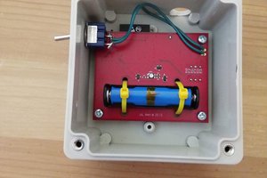
It is simple: every active beacon (locator) appears on a map and anyone sees its current position. The beacon is mounted on the aircraft (be it multi-rotor, glider, powered RC model etc.). Scattered on the ground are several receivers, connected to the internet. When a receiver gets data from a locator, i sends it to a handling server that places the drone on a map. How is this useful ?

Let's consider our case: we test our UAVs near a utilitarian airfield ...

Read more »

WildDrone Locator.zip

This ZIP contains the code for the transmitter and the receiver. Once again this is not my work. Everyone, say "Thanks!" to Alex.

x-zip-compressed - 1.03 MB - 10/01/2018 at 08:10

Download

WildDrone Locator Enclosure.zip

Enclosure project files (SolidWorks 2016).

Zip Archive - 1.47 MB - 09/30/2018 at 21:46

Download

sheet - 11.63 kB - 09/30/2018 at 18:52

Download

Complete WildDrone Locator PCB designfiles.zip

The complete design files: schematic, PCB, Gerbers and BOM.

Zip Archive - 20.73 MB - 09/30/2018 at 18:51

Download

LoRa Beacon.PDF

Schematic design.

Adobe Portable Document Format - 961.06 kB - 09/30/2018 at 17:58

Preview
Download

View all 8 files

  • 2 × CAP, MLCC, C0G/NP0, 20PF, 50V, 0603
  • 10 × CAP, MLCC, X7R, 100NF, 16V, 0402
  • 1 × LED; SMD; 0603; red; 10-22mcd; 1,6x0,8x1,1mm; 120°; 1,75÷2,2V; 2mA
  • 1 × Mini UFL rf conector.
  • 1 × Socket; USB B micro; PCB; SMT; PIN:5; USB 2.0 Power Management ICs / Power Supply Support

View all 32 components

  • 30th September: I'll be back!

    MihaiVDR09/30/2018 at 23:39 0 comments

    ...said Schwarzenegger once.

    With the contest deadline on my trail, I must conclude that the RF physics won this battle. I did a bit more testing yesterday with the bicycle around my region, but I only repeated the 3 km "performance" achieved at the beginning. LOS is not as easy to get as I initially thought.

    It sucks that I did not manage to put the thing aboard a drone and to create my own LOS.

    But that's a job for another day.

    It's almost 3 o'clock in the morning here and I'm glad that I managed to describe my work so far.

    This project will not be scrapped or shelved abandoned or whatever. Testing will go on and on, so stay tuned.

  • 27th September: RF investigation.

    MihaiVDR09/30/2018 at 23:31 0 comments

    Time is running out.

    I have managed to get data from a remote transmitter, but the range is poor. Might be the lack of LOS (Line of Sight) between the receiver and the transmitter, but I suspect something else.

    I brought the receiver and the transmitter at close range (that is 10 cm).

    The receiver displayed its RSSI: -44dBm.

    I moved 3 m away: -57dBm.

    I connected them together: -42dbm.

    The transmitter should send out 20 dBm.

    I fired up a spectrum analyzer at work and conected the RF output through -45dB attenuation. I centered the analyzer on 434MHzwith 100MHz span

    Fig. 1: Power output measurement, with 45dB attenuators.
    Fig. 1: Power output measurement, with 45dB attenuation.

    The marker peaked at -27.98dBm.Let's call it -28. Add 45 and we get 17dBm. Not bad, it migh actually output 20dBm, but the attenuators definitely have some tolerance and the thin coax cable is certainly not loss-less. I bought it from ebay.

    Let's try a different coax, maybe this one is of low quality and has high losses.

    Fig. 2: Output power measurement, -45dBm attenuation.
    Fig. 2: Output power measurement, -45dBm attenuation.

    With a new coax, the result is very close, but the soldering job at the board certainly dropped 0.2dBm. So the module outputs a decent amount of power and the cable is not as bad as I thought.

    Let's see what does the receiver receive. I borrowed a better pair of antennas from a colleague (thank you Marius):

    Fig. cx: NA711 433MHz antenna.
    Fig. 3: NA771 433MHz antenna.

    And I connected it to the analyzer, with no attenuation. I got -3dBm. Quite a loss from all those 17dBm, but still far away from the -44dBm returned by the receiver.

    Fig. 3: Homemade antenna and NA711 side by side.
    Fig. 4: Homemade antenna and NA771 side by side: -4 dBm.

    And I tried several other antennas:

    Fig. 4: Two Na771 side by side.
    Fig. 5: Two Na771 side by side.
    Fig. 5: 2xNa771 - Results: -1.5dBm
    Fig. 6: 2xNa771 - Results: -1.5dBm
    Fig. 7: 2 x 3DRadio 433MHz telemetry antennas.
    Fig. 7: 2 x 3DRadio 433MHz telemetry antennas.
    Fig. 8: 2 x 3DRadio 433MHz telemetry antennas. Result:
    Fig. 8: 2 x 3DRadio 433MHz telemetry antennas. Result:-1.72dBm

    Right now I wish I paid more attention at the Microwave course at school. We also had a class for antennas, but only theoretically.

    Something doesn't add up. The receiver's antenna gets around -1dBm with the better antennas, but is reports -44dBm.

  • 25th September: Long(er) range tests

    MihaiVDR09/30/2018 at 23:01 0 comments

    Still unsuccessful. I asked one of my colleagues that comutes 65km away by train to carry the transmitter in the backpack.

    He lives at the 8th floor, and he has no buildings to his south. The receiver remained at my workplace.

    It is almost line of sight, but not quite. Still, it is better than at my house.

    Fig. 1: 65km LOS (almost).
    Fig. 1: 65km LOS (almost).

    But no signal for the entire night. And not even from the road back.

    This needs some investigation.

  • 12th September: More range tests

    MihaiVDR09/30/2018 at 22:34 0 comments

    Using the same setup, I managed to get 3.5km from inside the car on the way home. However, it is way off the tens of kilometers claimed by LoRa.

    Line of sight is the answer. Andreas Spiess managed to reach a LoRa gateway 200km away because it was clear line of sight; from one mountain top to another. Here is the height profile of the 3.5km i managed so far:

    Fig. 1: Line of sight 3.5km.
    Fig. 1: Line of sight 3.5km.

    As soon as I turned East to head home, there was no more LOS.

    Fig. 2: Loss of LOS.
    Fig. 2: Loss of LOS.

    So there was no way to hear it all the way home (the green pointer):

    Fig. 3: No LOS at home.
    Fig. 4: No LOS at home.

    I should check other options....

  • 10th September: First radio tests

    MihaiVDR09/30/2018 at 21:57 0 comments

    We programmed one board to transmit it's position using LoRa on 434MHz and SF12 and the other as receiver. The coordinates at the receiver are hard-coded for now at our workplace. The receiver is plugged in a usb port and it acts a s a virtual com port.

    And here are first results.

    Fig. 1: Teminal output from the receiver.
    Fig. 1: Teminal output from the receiver.

    The receiver is mounted on a stick a the top of the hangar and I went for a ride with the bicycle. As you can see, I had my 6km exercise for today. Data rate is low: one message every minute.

    That RSSI is a bit low for this small distance ...

    I put the transmitter in an electrical junction box with 2 18650 LiIon cells in parallel. It must hold together for the rough testing coming it's way. The 3d printed enclosure is not as solid as it looks.

    Fig. 2: Junction box "bulletproof" transmitter.
    Fig. 2: Junction box "bulletproof" transmitter.
    Fig. 3: Junction box close-up.
    Fig. 3: Junction box close-up.

    I specifically not posted a picture of the receiver. Every viewer would laugh its ass off. Just imagine this PCB, with a 10m USB cable, a bare wire antenna sticking at the top, with a black garbage bag to keep rain away, everything held together to a wooden stick, with orange insulator tape. On top of a hangar. Quite an image, right ?

  • 6th September: 3D print ready

    MihaiVDR09/30/2018 at 21:42 0 comments

    I forgot to take some pictures during the print process and I went ahead and epoxied the insets and the button.

    I also glued with epoxy 4 nuts on the bottom part joining assembly.

    Fig. 1: Case and bottom cap.
    Fig. 1: Case and bottom cap.
    Fig. 2: Case and bottom cap.
    Fig. 2: Case and bottom cap.
    Fig. 3: Assembled enclosure.
    Fig. 3: Assembled enclosure.
    Fig. 4: Assembled enclosure.
    Fig. 4: Assembled enclosure.

    The right screw head makes all the difference in the world !

  • 5-th September: Enclosure design ready!

    MihaiVDR09/30/2018 at 21:31 0 comments

    Just as the title says: it's ready. I even created a logo. Probably not the most original logo: a paper plane and some arrows pointing at it. After all, it's a locator for small planes, right ?

    Fig. 1: The antenna comes out through a wall.
    Fig. 1: The antenna comes out through a wall.
    Fig. 2: The gray cube at the bottom is the LiPo cell.
    Fig. 2: The gray cube at the bottom is the LiPo cell.
    Fig. 3: The bottom is fixed with screws to the top, but the holes are extruded directly from the bottom part. As they are not overlapping, the holes do not appear.
    Fig. 3: The bottom is fixed with screws to the top, but the holes are extruded directly from the bottom part. As they are not overlapping, the holes do not appear.
    Fig. 4: Compact enclosure.
    Fig. 4: Compact enclosure.

    The logo extruded cuts will be filled with white epoxy. The button will also have an epoxy fill. most probably red. It will look like a record button, but hey, that's what it does in the end.

    Let's hit the printer...

  • 3rd September: Antennas

    MihaiVDR09/30/2018 at 21:22 0 comments

    I just discovered that I don't have any 433MHz antennas. So I must make some.

    Luckily, I had a few broken RC model receivers with long range antennas. I can modify those to run at 434MHz.

    A quick calculation shows that for 434MHz we need an antenna length of 164mm (at quarter wavelength). I would have liked to have enough length to create a half-wave antenna, but that should do it for now.

    It has a UFL connector already on it.

    Fig. 1: ~16.5mm antenna.
    Fig. 1: ~16.5mm antenna.

  • 2nd September: Solved!

    MihaiVDR09/30/2018 at 21:14 0 comments

    Yes, we solved it ! And here's how.

    Indeed, the almighty oscilloscope proved that the thought from the previous log is correct. The D5-R14-R15 divider does not drop below 0.4V long enough to turn the NCP705 off.

    And here is the work-around: a 1uF capacitor.

    Fig. 1: Additional 1uF capacitor.
    Fig. 1: Additional 1uF capacitor.
    Fig. 2: Additional 1uF capacitor, soldered in top of R15
    Fig. 2: Additional 1uF capacitor, soldered in top of R15

    We also modified the value of R14 (was 47K, now is 100K) and the reference voltage divider. The power-down did not work reliably at low battery voltages.

    Fig. 3: New reference voltage divider values.
    Fig. 3: New reference voltage divider values.

  • 1st September: Hardware problems

    MihaiVDR09/30/2018 at 21:03 0 comments

    Of course, if something goes right the first time, it means that there is something wrong with it! Turns out it's nothing wrong with ours. The carefully designed power-up circuit only does half of its job: turn-on is OK, turn-off is not. Oscilloscope and multimeter diagnosis show that the levels at the comparator pins are correct: when I push the button the voltage rises above the reference voltage created by the voltage divider.

    We suspect something else... We turn off the circuit by pulling down the EN pin of the LDO with the MCU. But the MCU's pins operate as long as it has a stable power supply. When the 3.3V drop. the pin becomes High-Z.

    The NCP705 has the Enable falling threshold at 0.4V. So the MCU releases the EN pin way before the 3.3V rail collapses and the divider with the diode keep the part alive.

    We'll think about that...

View all 21 project logs

Enjoy this project?

Share

Discussions

zmetzing wrote 10/09/2018 at 17:08 point

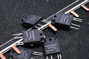
Reminder to those who will duplicate this design in the US: The 433MHz ISM band has emission limits on power and duty cycle.


https://www.edn.com/electronics-blogs/eye-on-iot-/4437311/Using-433-MHz-for-wireless-connectivity-in-the-Internet-of-Things

  Are you sure? yes | no

don.vukovic wrote 09/30/2018 at 22:07 point

What compiler/IDE do use for the firmware ?

  Are you sure? yes | no

MihaiVDR wrote 09/30/2018 at 23:46 point

Hello,

The code is written and compiled using Atollic TrueStudio for STM32, the free version. I must mention that I did not write the code myself, I had a lot of help from someone at work because I am way too slow with STM32 to be able to finish this before 1st October. We programmed the chip using a STlink.

  Are you sure? yes | no

Similar Projects

Does this project spark your interest?

Become a member to follow this project and never miss any updates