 Stephen Harrison
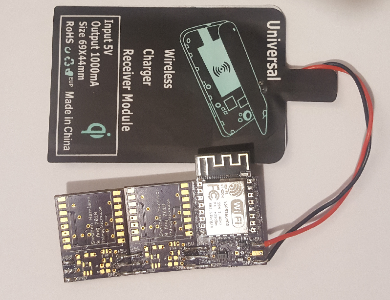
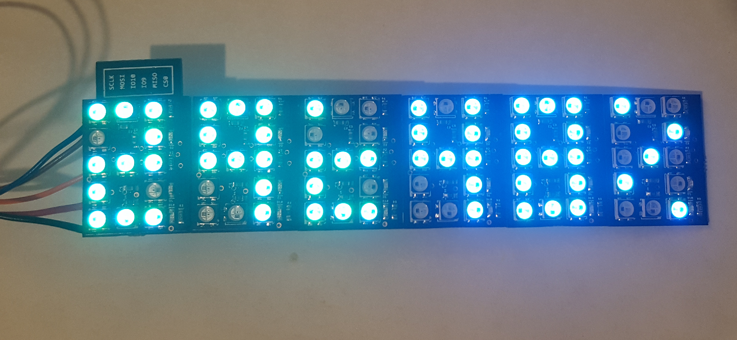
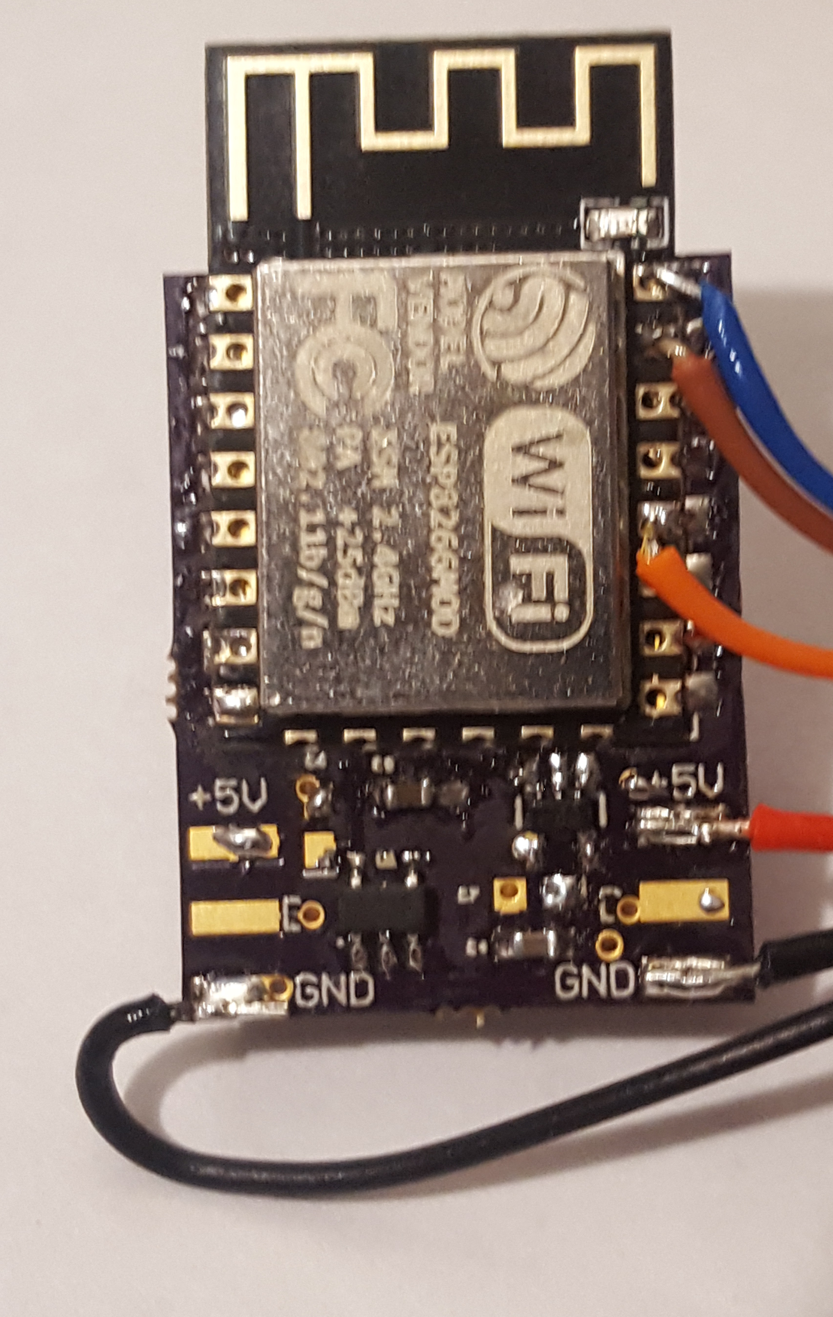
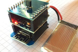
IO7 is a neopixel based 7 segment digit that has an on-board ESP 8266 (ESP12 module) for WiFi connectivity.
Each module may be either a fully built module with a WiFi module, or a secondary module with only LEDs to extend the display.
Modules are connected to each other via a 3 way solder connector at the bottom of the display allowing for a versatile, and flexible display.
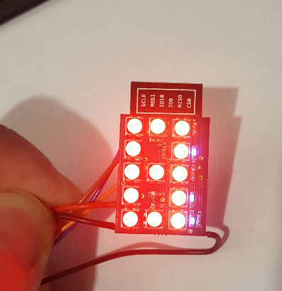
The parent IO7 has an ESP-12 (ESP 8266) module on the back for WiFi connectivity and for control of the LEDs, as well as 3 additional small (0602) colon and decimal place LEDs, both parent and child displays have "Neopixel" WS2812B 3535 size RGB LEDs on the front to make up a 7 segment display.
Each pixel in the 7 segment display may be individually controlled for colour.
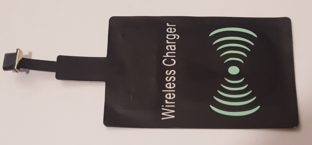
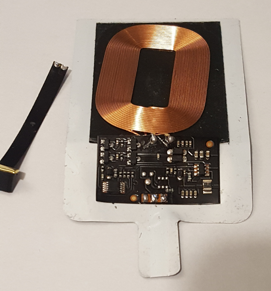
With the addition of a battery or QI wireless charger the system can become a truly wireless Internet connected display.
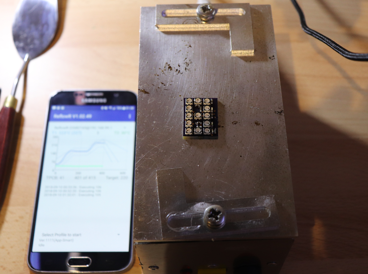
In the pictures I've connected the module to the Tinamous.com MQTT server and subscribed to temperature and humidity feeds from a Particle Photon powered ThingySticks Air Quality sensor.
 Radu Motisan
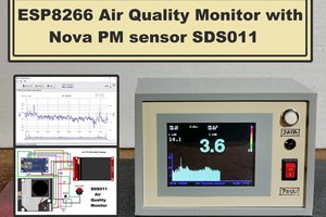
 mircemk
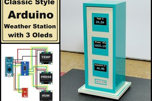
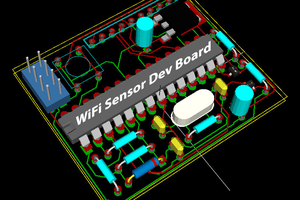
 Michael O'Toole