 Jack Flynn
I've had a lot of fun playing with the LEDs. As of this moment each LED is connected to a pin on the Teensy. In the future, as the number of LEDs grows, I'll need to use a buffer chip of sorts to prevent running out of pins or over current draw from the Teensy. For the code I've created wrapper modules to make controlling the LEDs easy with the Teensy and they should be upgradable when I change control method.
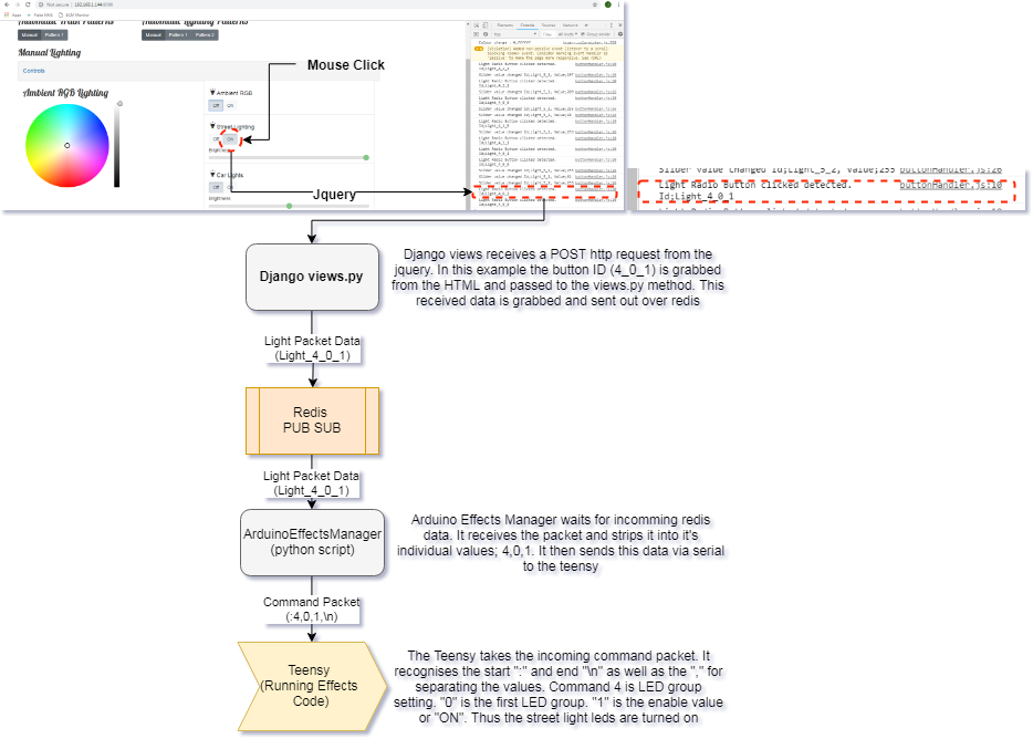
Before writing this log entry I had the LEDs switching on and off as shown in my previous entry. This shows that the logic control for the LEDs is working and we have that instantaneous control. How this is achieved from mouse click to LED "on" is detailed below;
The Imperfect World
LEDs are a perfect example of a digital device. They are generally on or off without any variation of power in the middle; as soon as you apply a voltage above a threshold you get full brightness depending on the allowed current usage. This is great for fast paced, reactive interfaces; nothing catches your attention like a blinking LED. However in the real world of lighting, particularly older homes and street lights, this on-off flip to full brightness isn't achieved instantaneously. It takes time for normal bulbs to warm up and produce their full brightness, perhaps this isn't ideal in the real world but aesthetically it's comforting and more natural than instant "LIGHT!". With this in mind can our LEDs replicate this imperfect "warm up"?
Trick of the eyes
Again, unlike the analogue world of bulbs where we can use a variable resistor (dimmer) to vary our brightness, the digital world of LEDs requires a more complex solution to allow for "dimming". As stated an LED is either on or off, this is fact, but our eyes are easily deceived. Blink an LED above 60 blinks a second and what should be on-off-on-off appears to our eyes as constantly on; this neat little trick can be seen here:
(red flashing 1/s, yellow 10/s and green 60/s - not as easy to see as the yellow is brighter)
The code to achieve this effect is really simple. We're just turning the LED on and off and on again 60 times a second.
/*
Based on "Blink" example.

Runs 3 LEDs blinking at different rates dependent on timers.

The "on" and "off" period are the same amount of time.
 */

int Redled = 6;
int Yelled = 5;
int Grnled = 3;

boolean RedState, YelState, GrnState = false;

int RedRate = 1;
int YelRate = 10;
int GrnRate = 60;

// the setup routine runs once when you press reset:
void setup() {
  // initialize the digital pin as an output.
  pinMode(Redled, OUTPUT);
  pinMode(Yelled, OUTPUT);
  pinMode(Grnled, OUTPUT);
  Serial.begin(115200);
}

// the loop routine runs over and over again forever:
void loop() {

  static unsigned long RedTimer = millis();
  static unsigned long GrnTimer = millis();
  static unsigned long YelTimer = millis();

  //Timer for red led
  if(millis() - RedTimer > 1000/(RedRate*2))
  {
    RedState = !RedState; //Flip value of RedState
    digitalWrite(Redled, RedState); //Write to pin
    RedTimer = millis(); //reset timer
  }

  //Timer for Yellow led
  if(millis() - YelTimer > 1000/(YelRate*2))
  {
    YelState = !YelState; //Flip value of YelState
    digitalWrite(Yelled, YelState); //Write to pin
    YelTimer = millis(); //reset timer
  }

  //Timer for Green led
  if(millis() - GrnTimer > 1000/(GrnRate*2)) //need to double the rate as this covers "on" and "off" cycle
  {
    GrnState = !GrnState; //Flip value of RedState
    digitalWrite(Grnled, GrnState); //Write to pin
    GrnTimer = millis(); //reset timer
  }
}
Dimming by PWM
So blinking really fast allows us to trick the eyes into seeing a constantly "on" LED but we still don't have control over the brightness. The answer lies in "PWM" - Pulse Width Modulation. We're basically taking the "blinking-really-fast" trick and adding another layer on top. Previously when we were blinking the LED we had the same amount of "on" and "off" time. This is known as a 50% duty cycle where the pin spends the same number of milliseconds off as it does on. By varying the duty cycle we can create uneven amounts of "on" and "off" time and this gives us our brightness control; 10% duty cycle means the pin is only on for 10% of the time creating a dimmer light, while a 90% duty cycle creates a much brighter light by having the pin on 90% of the time. By design microcontrollers have this duty cycle method of pin control , PWM, as a standard feature and the Arduino makes this really easy to use. The standard PWM module of an Arduino runs at around 1kHz so we're well above our 60 blinks a second and by selecting the PWM capable pins (marked on an Arduino with "~") we can use the analogWrite method to control the brightness of our LED. Varying the analogWrite value varies the brightness and bringing it all together we can create our nice "warm up" effect with the lighting in our project.

(oof that gif did not compress well)
//************************************* Uses the same setup from before
// the loop routine runs over and over again forever:
void loop() {

  //Brigthen red led
  for (int i = 0; i < 255; i++)
  {
    analogWrite(Redled, i);
    delay(10);//reset timer
  }

  delay(500);

  //Dim red led
    for (int i = 0; i < 255; i++)
  {
    analogWrite(Redled, 255-i);
    delay(10);//reset timer
  }

  //Brigthen all leds
  for (int i = 0; i < 255; i++)
  {
    analogWrite(Redled, i);
    analogWrite(Yelled, i);
    analogWrite(Grnled, i);
    delay(10);//reset timer
  }

  delay(500);

  //Dim all leds
    for (int i = 0; i < 255; i++)
  {
    analogWrite(Redled, 255-i);
    analogWrite(Yelled, 255-i);
    analogWrite(Grnled, 255-i);
    delay(10);//reset timer
  }
}
Discussions
Become a Hackaday.io Member
Create an account to leave a comment. Already have an account? Log In.